Need to go backward to move forward.
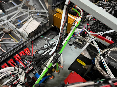
Because I used a plexiglass firewall for mock up, it needs to come out. Which means the engine, engine mount, firewall frame, coils, regulator, pumps filters, batteries, ground block, relays, shunt, etc, etc all has to come off. The good news, this is the last time (fingers crossed - hopefully I didnt just jinx myself).
Couple things to do before it all comes apart.
- Determine final location of fuel return line through firewall, and make hose back to top of header.
- Cabin heat pass through
- Alternate air pass through
- Throttle pass through
Ready for removal
Few things to do, then the firewall gets completely disassembled.
One of the challenges is how to cut the big 2" holes (one for the umbilical, and one for the cabin heat duct). Cutting holes is easy, as long as its not stainless. My hole saws are of a fine 'Princess Auto' variety (think Harbor Freight).
Looking at the Glasair forum, there are so many opinions on how to cut them. The TWTT instructions say use a hole saw over 1", and a unibit under 1". My el cheapo hole saws made a lot of smoke and just dinted the material.
After consulting the forum, I decided to try a carbide tip hole saw and a punch.
Pretty much immediately, the punch started to warp the stainless - and it never fully went all the way through. So those are going back to the store...
As a side note, I bought a new unibit... Millwaukee 'no jam' unibit. Cuts stainless like butter.
Piece of cake. Cut the 2" hole in about 4 seconds.
From there I used a drum sander to clean it up a bit. The carbide hole saw is the solution...
Firewall disassembly begins...
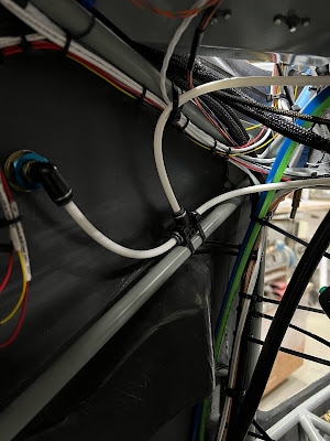
Completely naked... I had to pull all the wires / hoses, etc back through the firewall. This will be an awesome opportunity to clean up the wires, etc I could not reach.
Firewall in place (thanks John!). I just hope it will fit once the blanket is adhered to it. Fingers crossed.
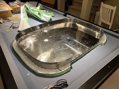
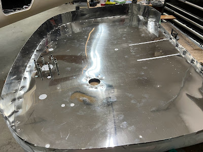
Firewall blank with the plexi kinda laying in front of it. I need to finish disassembling everything on the plexi.
Next is drilling. As a test I tried the carbide bit with a hand drill today on a test piece. Oh no, bad idea. On the flip side, I did some 1" holes with the Millwaukee unibit in the drill press. Super nice. I think I have it all worked out now (fingers crossed).
The small holes - less than 1" were pretty simple. the 2 big 2" holes were a bit more challenging. The engine umbilical (which is up high on the firewall) was pretty easy, as I could do it in the drill press. The 2" cabin heat hole was more challenging, as it would not fit in the drill press. So I ended up essentially scoring it with the 2" hole saw with a hand drill, and then drilling a series of 1/8" holes around the perimiter, joining them with the dremmel and a cut off wheel, then smoothing them out with a carbide bit in a die grinder, then finishing with a drum sander.
Next problem(s)...
- I had planned on using the cable safe and cable safe II fittings for cabin heat, alternate air, and throttle. Well, they are aluminum and won't pass inspection. Need another solution. However, after talking to my inspector the cable safe fittings are acceptable.... so..???
The above is the firewall closeout for the UL umbilical (described in previous post). I ended up making an aluminum ring for the back that will be riveted to the firewall. The stainless C shaped disks will be screwed through the firewall to the aluminum disk (with captive fasteners). Hopefully this all works out.
Firewall flanges riveted.
The rivets supplied with the kit are Monel (aka stainless), and are SUPER HARD. Definitely a 2 man bucking requirement. Of the 54 rivets for the firewall, we had 2 bad ones that needed to be drilled / replaced, and 1 smiley.
Finishing up all the firewall aft brackets for the relays, cabin heat box, and engine umbilical pass through. Then I can finish them (IE clean, alodyne, paint, rivet fasteners). Then its onto the firewall blanket.
Test fit of the frame. There was a couple holes I forgot to drill in the stainless and needed the pattern.
Then I had a nightmare... I could not remember if I had fit the air deflector with the frame and gascolator on.
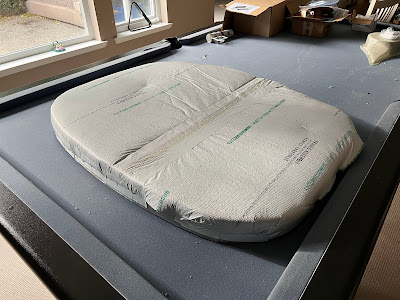
Insulation blanket cut in half and taped both sides. The TWTT instructions do not say much other than 'cut in half, tape the two halves together'. The manufactured edge of the material does not have insulation (see below pic).
The solution is to overlap the manufactured edge and butt the insulation up against each other, and then tape both sides.
Insulation initially cut to fit. Supposed to trim to 2", but I did slightly more, so need to correct.
I did the bulk of my wiring with the temporary firewall in place and the engine hung. Now that all of that is out, now is the right time to clean up the mess and finish the last few connections. I am actually rewiring all of the power connections through the firewall. All of the new wires are extra long so I can route them nicely and terminate appropriately. Its only about 10 wires... a few of them I had not done yet, but those are in progress.
Insulation adhered to the firewall, and orcotek tape in place. I am about 4' short (ordered 10' from Glasair for $40). The kit came with 16', but if doing 2 lines of tape from top to bottom on both sides when joining that is just not enough. If you only do one side (which the TWTT instruction indicate), 16' would be enough. I probably messed up about 1' of it where it folded over on me and I could not recover it. The best method is DEFINITELY to do it in short strips and not try to wrap the entire ~12' of firewall in one piece (this tip came from the forum).
Top side...
Bottom side
There are a few puckers here and there, but once it is pressured up against the cage I am hoping they will come out. Not that much will be visible when all is said and done done.
I've made back plates for the captive fasteners for the relays, engine umbilical, and cabin heat box. These have all been alodyned and primed / painted. Next is to rivet the fasteners in place, then rivet them in. Also have large washers for the throttle pass through, UL pressure lines, main fuel line / return line.
Time to put all the fasteners in.... luckily they can all be squeezed and no bucking required.
Only 1 plate to go, then its onto ground blocks, pass through fittings, etc.
Good day today. Everything is mounted except the -6 fuel return line and -8 fuel delivery line (ordered the wrong stupid fittings).
Everything has loctite applied to the fasteners that will be inaccessible after installation.
Rear view
There is a bit of slack in the insulation (which is a good thing). Once it is pressed up against the cage, the slack should be taken up nicely (fingers crossed). There are 8 cage attach points, plus 5 for the engine mount, etc. Plus, you wont really see much of this anyway.
I think that is enough for one post...


