Search This Blog

Showing posts with label Intercooler. Show all posts

Monday, 6 January 2025

Engine install completion - lots of little stuff

Working on finishing the engine install, and planning on running it when complete.

First item is the starter.  Having a dual battery system with 2 master relays means I have to pull off the 'bridge' between the two relays for the starter (so I can start on either or both batteries).  Been debating for awhile how to accomplish this.  Finally decided on a 4 position terminal adel clamped to the engine mount close to the relays.


Next is the air / oil separator.  There is no 'good' location... but finally just did it and will adjust later if necessary.  Per the UL manual, you want an uphill slope from the engine breather to the separator, and a downhill slope from the separator to the return.  I think I have this figured.


Back to an old problem... there was an issue with the oil return line from the air/oil separator that goes back to the sump.  I think it was bent, and got a replacement.  But I never finished installing it for some reason.  Need to get this fixed before putting oil in.  I did not put the screw back in that secures it.  I think that was because the oil line for the turbo needs to come off to do so... so that will be a job.

EGT's and CHT's are all installed.  Vacuumed out the exhaust by removing the waste gate to get any chips out so they do not get into the turbo.  I didnt hear anything when doing this...  

I checked the EFIS to see what the sensors were reading, and they were all not reading anywhere near correct.  Asked Advanced, and there was a bug with UL engines and direct read from the EMS.  New software obtained that fixes it (AF5000VX161036B06-MV16.afz).  Installed today, and works like a charm.  All probes are reading 'ambient-ish'.


Plug wires... I have been dreading this.  Like really dreading.  Making them looks right, not be a dogs breakfast all over the place, and was super worried about the electrical connections, etc.

So far, initial impressions are UL has this figured out.  One end is crimped, and the other end (engine side) has like a screw terminal inside the plug wire housing.  You literally just thread it in.

I labeled everything... which ignition it is coming from, and what plug ig goes to.  On both ends.  Yes, this is overkill...  Forward plug is ignition 1, aft plug is ignition 2.  Finished one side (3 cylinders, both plugs) in an afternoon.


Another builder and I had toyed with using the cross bar of the intercooler to organize the plug wires with some 3D printed parts.  I decided to go cheap and fast and just use HD plastic.  Used the grommet from the engine kit that goes in the aft end of the baffle as a template.  Small piece of angle aluminum and an adel clamp, and its done.


Exhaust pipes back from the ceramic coating.


Need to secure the bottom of the exhaust.  Brackets on the exhaust already installed.  Used the RV 'trick' of a thick hose as the support brace, with some stainless tabs on the end.  Need to get the correct hardware.


Fit the cowl, spinner and prop.  Lines up pretty good.  Not quite perfect, but close.


I started torquing the prop... but then found out (thanks Paul) about Service Bulletins from Airmaster.  One applies to me... brushes on the pitch change motor.  Email sent to Airmaster... my serial number is on the list.  Need to determine if the whole things comes apart again or not.

Brake lines from the park brake out are complete.

Turned the engine over from the starter with 6 plugs out.  Turned over great!  But... no oil pressure reading.  Talked to Ray... I turned it over for about 20 seconds.  Needs more than that.  Adding to the to do list.

The engine ground wire location is beneath the starter on the right hand side of the engine.  Long wire, pain to fasten.  Found an M8 threaded hole on the left side of the engine... shorter run, easier to install.  Seems to work great.

All lines are secure.

Shortened and rerouted the engine ECU to throttle body line.

Last thing is to obtain more hose for the breather and install.


'Almost ready to fly' my ass.  This has been a lot of work, and a lot of custom work.  Between the cowl, bracketry, exhaust, electrical system changes, this beast has taken a very long time.

Now onto the rest...


Monday, 20 May 2024

Intercooler - Part II


Intercooler, plenum and ducting moving along slowly.

Spend the day yesterday getting the brackets, plenum, etc all ready for paint.  Finishing up all the drilling, deburring, fastener prep, 3" holes for the ducts, acid etch, alodyne, etc.  I thought it would take an hour... 4 hours later...  Everything is primed and paint is going on now.

I decided to use epoxy primer this time rather than zinc chromate.  What a difference... the primer sticks better, and the paint goes on REALLY well on top.


Next is riveting... 


Intercooler bracket all riveted with nutplates installed.


Plenum and flanges riveted.  Test fit on the bottom bracket.  All good.


Test fit on the intercooler.  Snaps right into place.  One tiny interference issue on the intake tube.  Fixed.


Bonded in place using leftover firewall silicon goop.  I also put a small bead of the goop on the seam on the inside of the plenum.  It shouldnt leak much, but every little bit helps.

Installed...


Its a bit of a puzzle to install.  The intercooler (minus the plenum) fits right in no problem.  But to get the plenum in, the intercooler needs the bottom mounts free, and the top mounts loose.

So onto the intercooler inlets.  My plan is to use the outside of the cylinder inlet D and feed it to the intercooler.  My first attempt at this was MDF and dry wall mud - dont do that.  It worked, but took forever to dry and cracked a lot.  I finally finished it weeks later.

For the other side, I used foam - 1/2" foam to be exact, and cut / laminated it.  Here are the two of them side by side.  The white one is the MDF / drywall mold (starboard side), and the foam one is in its early stages (port side).


I am going to lay it up in three separate pieces, and then bond them together - top, rear and bottom.  I know this is not ideal, but I dont want to destroy the mold.

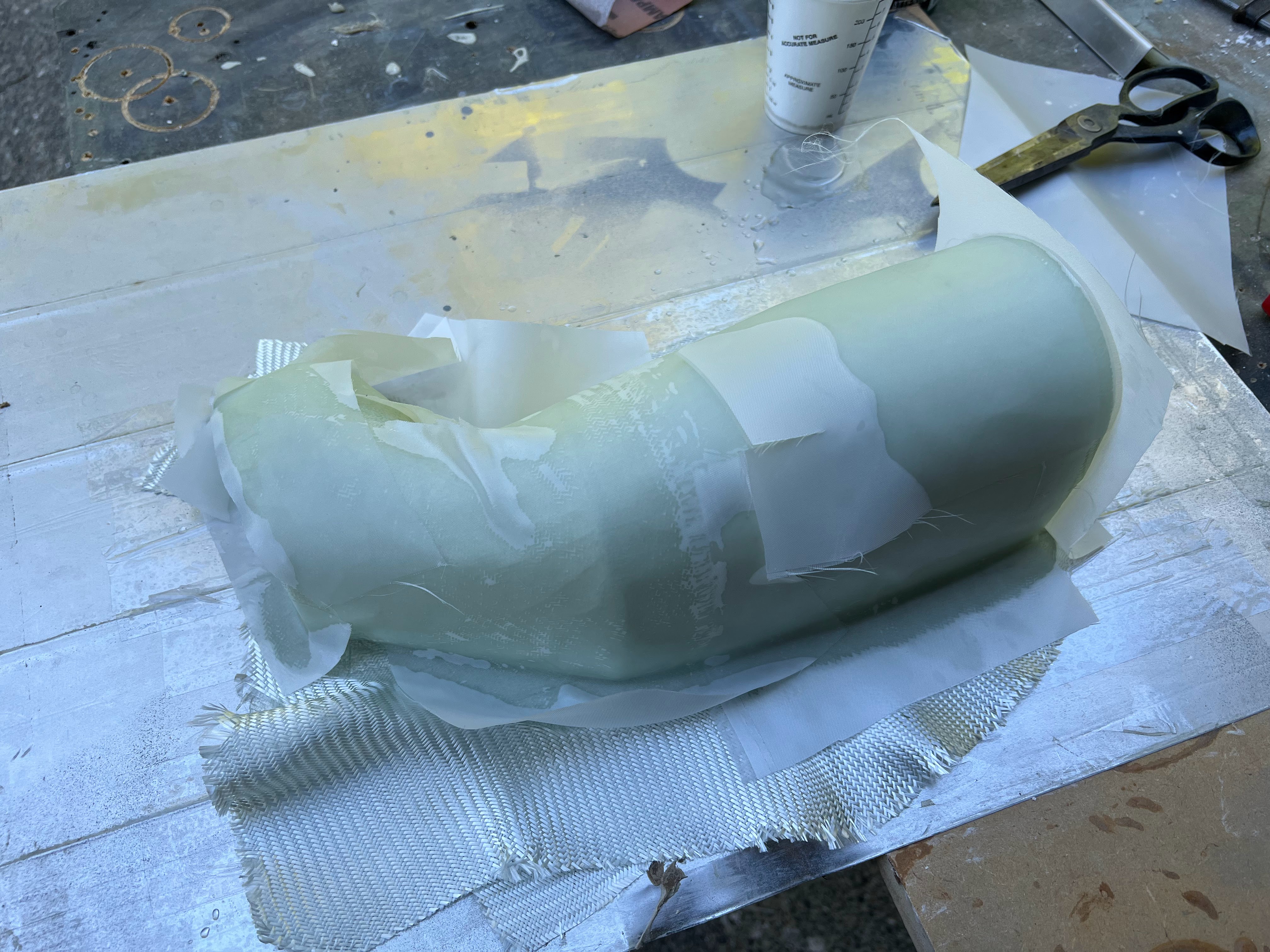
First piece laminated up.


Part extracted from the mold with only minor mold damage.


Next:  I chopped off the rear flange (which was not usable... all the cloth was gathered there from the sides).  Put the part BACK on the mold (after some minor repair), and layed up 3 layers of glass on the rear, plus another layer on the top 2" to bind it all together.  Then another 2 layers on the leading edge to make it stronger as it will be sitting in the airflow at the front and want it super stiff.k

Part came back out of the mold with a little bit of poking and prodding.  It now has a new back and reinforced front.  Next is to make the bottom.


My plan is for the bottom to slip over the top.  I will bond them together with resin / cabo and cleco.  Once dry, I will put another layer or two of glass over the seam.

To make the bottom fit over the top, I have to build out the bottom slightly.  The glass thickness is about .04.  4 layers of tape is about .012.  So I need around 10 layers of tape to build up the edge enough that the bottom will slip over the top.  The only place this is critical is the rear as the back has structure.  All the rest of it will just conform, but figured I would try to do it right since I was already at it.

Bottom layed up.... fingers crossed.


Back extracted from the mold after lots of gentle nudging.


The sides need to be trimmed down obviously.

The first mold is very heavy and strong, which made it easy to get the part out.  I am somewhat worried about the foam mold.  It is fairly strong, but much more fragile than the first one.


Top and bottom temporarily fit together.  I think this is going to work out just fine.

I have been staring at how to mount this to the side of the plenum for quite some time.  I want it to be removable.  Since the beginning have been planning on using 2 of the 3 bolts that hold them plenum sides on.  Dawned on me the other day to use the holes that hold the top on a well.

So the plan will be an aluminum bracket (probably 0.063) that will go between the top and bottom mounts.  Then I will position the intercooler plenum, and both bond and rivet it in place.

After a lot of staring and wondering what to do, and talking to a hanger mate about his project I thought about 3D printing the forward plenum.  Talked to a friend that used to teach 3D modeling and printing at a local high school.  He accepted the challenge to design these up for me.


Ordered a test part through Xometry - which claims to be the uber of 3D printing.  Ordered on a Sunday with their slowest / cheapest option.  Shipped Thursday from MI via ground.  The top and bottom were $297 USD including shipping.  I checked a number of Canadian 3D printing shops, and the cheapest price was $500 CAD.

Parts arrived...


There is a small amount of interference at the front between the bottom and top of the plenum.  This should be easy to fix.


Rough positioning to see how it fits.  There will be a 0.063 plate that the entire assembly is attached to, so it will be offset outboard.  Also planning on an air gap to protect it from the heat after shutdown.

Plate made and clecoed in.  Duct clecoed in.  Nothing is final final, as I need to make a few filler plates to make everything be perfect.


Honestly, I think its pretty good.  You cant see it in the photo, but there is an air dam that comes out from the duct into the fiberglass inlet to channel the air either to the intercooler or cylinders.  I like this way more than my crappy fiberglass parts.  Need picture with cowl off.


Almost all of the baffles and ducts are fit.  3 small ones to go, and everything is rough installed.


All done and fits.  Had to trim the cowl a bunch... but its done done!


Friday, 26 May 2023

Intercooler


I ordered the intercooler from UL Power USA in the summer of 2022 when I ordered the prop.  Due to supply chain issues, price increases, change of vendors the brass tacks are finally hitting in late January / February of 2023.

The question was... orientation of the inlets and outlets.  The other Sportsman that is flying has his intercooler up high in the engine bay, aft of the engine, just under the engine mount.  He has air temp issues, and is trying to get more air to the plenum.

My tentative plan...

  • Enlarge the front openings in the cowl slightly
  • Use ~1/3rd of the opening to feed a 3" scat tube on each side.  Run that scat pipe in parallel with the cylinder heads and feed a plenum attached to the intercooler.
  • The big reason for doing this is it will all be fixed to the engine / baffles.  There will not be any hoses (well, other hoses) attached to the cowl, so the top will just come right off.  At least that is the theory / plan.
The plan has one potential flaw.  The plenum will be on the back side of the intercooler and push the air forward, and it will hit the ring gear.  The alternative is to push it back into the pumps, filters, and coils.  That is a bad idea...

Putting it on any angle just spreads the heat.  I think having it hit the ring gear (and mix with all the air coming down from the cylinder head baffles and go out the bottom) is the best compromise.

Below is the drawing I received from UL...


I mocked up the basic dimensions in cardboard so I could play with it.  So it was arts and crafts day... the dixie cups are the inlets / outlets.  I really wish the engine was on so I could play with it a bit more...

Note:  I had not planned on doing this, so I hurriedly clecoed in the firewall frame and engine mount.  This all has to come back off again... unfortunately.


The turbo that feeds the intercooler is on the starboard side of the plane, on the aft side of the engine.  The throttle body is on top of the engine, aft end.

Based upon what I know and what I can see, going straight up and down is the way to go.  1 90 degree bend from the turbo to the inlet, and then 2 90's from the intercooler to the throttle body.

Its always so much easier to say things like this... harder to achieve.

Intercooler has been ordered with 2 straight fittings going straight up.  I sure hope this is the right choice (I say that a lot...).

Now it's time to wait.  Lots can be done between now and then.

Intercooler finally received in April (3 months later...)


Mounting this beast is going to be a B$#&H.

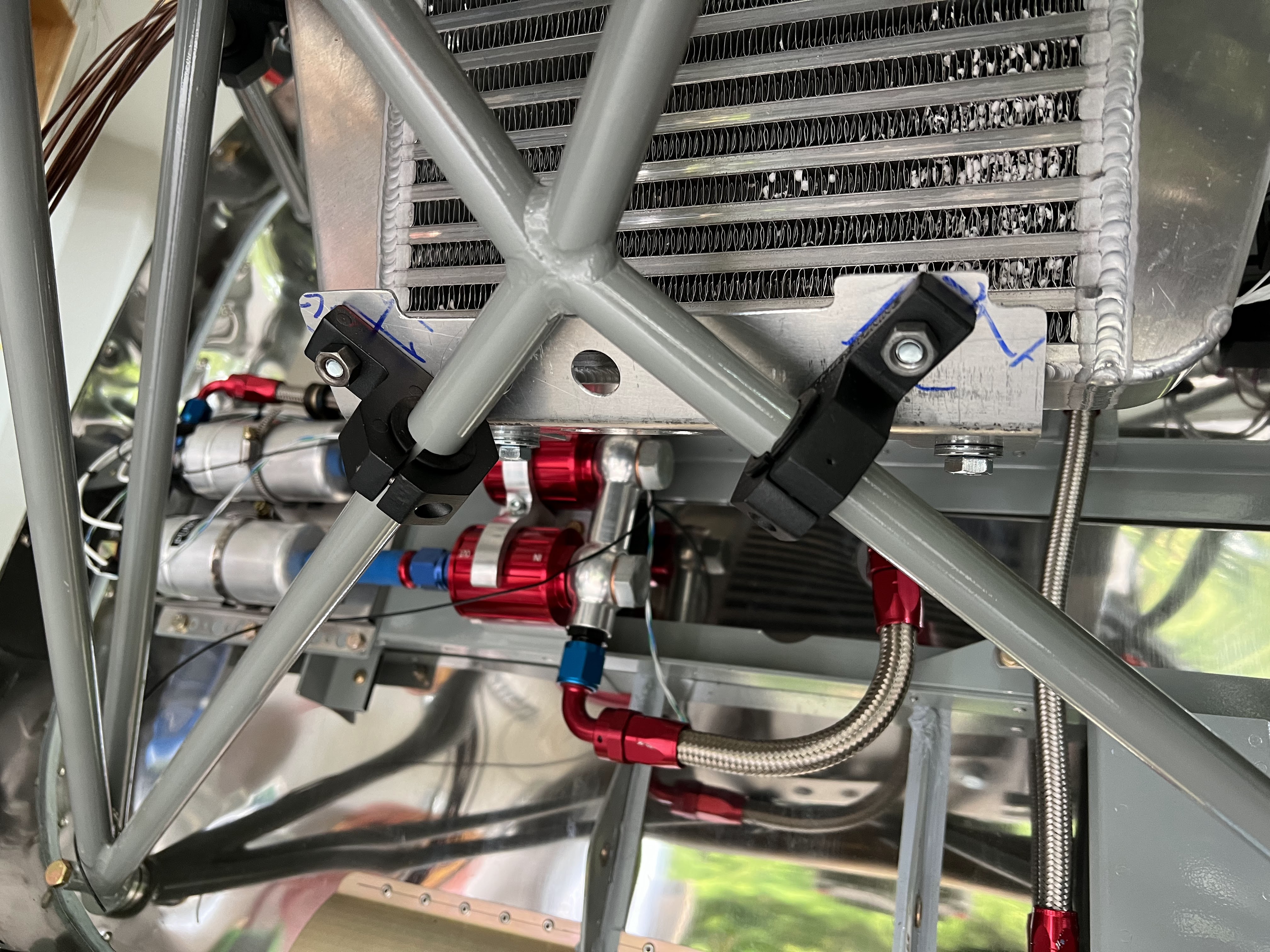
I bought some role cage mounts on amazon.  My tentative plan (until a better ones comes along) is to use 1" tubing, press the ends flat, and mount to the brackets clamped to the engine mount.  Like this.


Then weld brackets on to the tube at the correct angle for the intercooler.  I will probably have to tack them in place to get the angles right.

Fast forward a month or so... I have been working on the positioning of the intercooler.  Moving the bar back and forth to get the right angle to the turbo (so a 90 degree 2" hole will connect), positioning the intercooler left and right to not hit anything, etc.  The mount for the bar is now 11.25" along the engine mount from the firewall bolt head on both sides.  I moved it about an inch farther back.  The top cooler mount brackets are tie wrapped on so they can be moved.


I was a bit concerned with engine shake (on startup) after watching a 4 cylinder UL bounce around when the cowl was off.  Asked another Sportsman / UL builder how much room he has between the turbo outlet and the engine mount (I have 0.5").  He has less, and it has never hit and the engine does not shake.  Moving on.

So now its positioned fairly well, need to make the bottom bracket.

My original plan was to have a cross tube for both the top and bottom mounts.  However the top is so strong, having a 2nd one would be complete overkill.  So the bottom bracket will just be a bent piece of .063 aluminum to pick up the bottom brackets.


I will trim it down to reduce weight.  Just wanted to get it positioned and drilled.

Trimmed down with a few lightening holes.  May add a few more...


The mounting is nice and stiff.  It's not going anywhere, which is the point.

For the outlet of the cooler to the throttle body, I need 3 bends.  I also have to reroute the engine umbilical slightly. 

I bought 3 90 degree bends and cut them up appropriately, with a 2.5" piece of 2"OD aluminum as a coupler.


Next is the plenum.  Goals:
  • Light as possible
  • ability to remove when installed (I dont have enough room to get both the intercooler and plenum in together without taking off the engine - not enough room) on the cooler.
  • Leave room at the back to access the filters, etc
  • Flat side pieces for the scat tube inlet.  I want the tubing as big as possible - ideally 3"
I know there are so many ways to build a mold.  I used MDF (aka particle board).  Its strong, straight, easy to work.  I'm calling my mold the dog house (for obvious reasons).


My original plan was just to wrap it in packing tape and lay it up.  But, I know it will come out better if I properly finish the mold, fill the gaps, paint it, etc.  So I am.  All filled and ready for sanding.


Using a paint and primer in one... will need a couple coats and sanding.


Next it to build the bracket that will capture the plenum on the intercooler.  The one data point I have simply RTV'ed the plenum to the intercooler.  That is not my plan.  

My plan (hopefully) is to build a bracket that wraps around the intercooler with flanges that captures the plenum.  That way its removable.

The starting point for the bracket is to simple mimic the shape of the intercooler.  Again, I built the mold out of MDF, cut the fiberglass, coated it with resin and waited... and waited.  It never hardened.  I took it from a brand new can that I thought was promoted - it was not.  So mixed a test batch of 100g and promoted it and activated it, worked fine.  So cleaned everything off and tried again.


This is too large and will be cut down to fit, and will have a big hole cut in the middle.  Bottom line, this will wrap around and seize the intercooler and have flanges to capture the plenum.  Add a dozen or so nutplates and the plenum will be removable.  2 layers of bidirectional glass, with some peel ply on top.


Well, failure.  The part wont come off the mold.  I tried everything I could think of, and the part and mold are damaged beyond repair.  Time for plan B - aluminum.  Going to go with the same basic design.

What I did wrong:
  • The mold was too strong.  There was no way to get the part off.  No way to wiggle it out.
  • I used wax, and probably should have used mold release.
  • Should have made the mold out of foam so I could chip it out.
The big issue seems to be the corners, which are rounded with a 1/2" radius.  There is 4 layers of glass on all the corners.  Its super strong.

I have wasted about 3 half days on this.  Very frustrating.


The layout for the end caps will be the most challenging.


Looks about right.  Now just need to drill it.


So it fits in the spot intended and there is enough room to get stuff in and out.  The intercooler goes in first and the hoses attached, then the plenum will fit up through the bottom.  Attaching it will be a bit of a challenge.

New mount received that is made from 4130.  New holes drilled, and mounts tacked in place (forgot to take picture).  Now its onto finish welding.

Progress made on the plenum mount for the intercooler.


The plan is a C shaped bracket tha wraps around the intercooler.  The holes above are for the intercooler mounts.

After bending.  Note:  I have to cut a window in the mount for the cooler.  Have not gotten to that part yet, but will.


Fit to the intercooler.


Now its onto how to mount the plenum to the bracket (that wraps around the intercooler.

Because of restricted access, I am going to try and make a slot at the bottom that the plenum slots into.  The top will just be a flange with nutplates.


All of the bracketry is going to be flush riveted on the bottom, as it has to sit against the cooler.  I cant assemble the whole thing together now until its riveted.

After staring at the intercooler bracket and looking at the best way to attach it to the plenum, I decided to make a new one that is slightly larger on the face of the cooler.  It just wasnt wide enough to get some flanges installed and have everything tight, so I made a new one that is about an inch wider.  To do so, I have to go around the inlet and outlets on the top.


This time I precut the window for the cooler element.  I could have cut it after, but much easier to do before its bent.


Fits well.  Needs a bit of trimming here and there, but I have enough meat on the sides now to attach some angle brackets / flanges to grab the sides with nutplates.

As a side issue, noticed that the Advanced Flight Systems implementation of the UL CANBUS stack is missing the manifold air temperature.  This will be key in assessing the efficiency of the cooler.  Feature request submitted to AFS to add this data point.  Advanced says 2 to 3 weeks until beta software that includes the feature!

Flanges installed on the new plenum mount.


Upside down view.


The next step will be the intakes for the plenum, and I'm not sure what size yet.  This is going to sit now until I get the baffles on, and cowling fitted.