Yesterday (Fri, Feb 4) I picked up my panel / avionics from Advanced in Canby, OR. Nice 1100KM round trip single day...
The folks at Advanced were excellent. Dove into any question, and if someone didn't have an answer they went and found who did.

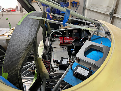
We went through every item line by line, then boxed it all. There is so little metal left in the panel that it is very floppy, and will be until it is mounted into the carbon fibre shell.
Next task is cutting the carbon shell. I am not looking forward to this...

Plan is to drill all the mounting holes first, then with everything clecoed in place mark the edges of what needs to be cut. Then mark out a real cut line, drill the corners, and then go at the straight pieces with a Dremel with a diamond bit.


After first batch of cuts... Carbon fibre is way itchier then fiberglass.

When I started drilling for fasteners, the clear on top of the carbon started to lift in some areas. Some parts of the panel are fine, some its just flaking off in chunks.


I put a support request in with the factory, and had a phone call that same day. Prep (or lack thereof) is the most likely culprit. Once I finish all the cutting / drilling / fasteners Glasair is going to re-clear it. I just have to get it to them. Very impressed with the support.

The nice thing about the shelf concept is I will have LOTS of room for all the boxes... of which there are many.

| Item | Description | Quantity | Proposed location | Dimensions |
| AF5000 backup battery | Left shelf - under | |||
| ADAHRS-200 | Primary ADAHRS | 1 | Center shelf - right | 4.71" x 2.61" x 1.22" |
| ADAHRS-200 | Backup ADAHRS | 1 | Center shelf - right | 4.71" x 2.61" x 1.22" |
| EMS-221 Canbus Engine Module | Advanced Canbus Module - to talk to UL ECU | 1 | Center shelf - right | 6.35" X 2.99" x 1.09" |
| ADSB-472 | Skyview ADSB 472 Dual band | 1 | Right shelf - top | 4" x 2.79" x 0.97" |
| GPS-2020 | ADS-B 2020 GPS Receiver Module | 1 | Left shelf - top | |
| PDA360XR | Remote Audio Panel | 1 | Right shelf - under | 7.64" x 5.82" x 1.34" |
| ACM | Advanced Control Module | 1 | Center shelf - right | 9.94" x 6.85" x 0.88" |
| Shunt | 60A Ammeter shunt | 1 | Right shelf - top | 5.9" x 1.96" x 1.18" |
| UL ECU | UL Power Engine Control Unit | 1 | Center shelf - right | 5.2" x 4.25" x ? |
| UL Boost Controller | UL Power Boost Controller | 1 | Center shelf - right | 1.53" x 2.56" x ? |
| Cockpit Ground Block | Ground block inside the avionics section | 1 | Left shelf - top | 6.4375" x .9375" x 1.03" |
| TCW Backup Battery | 6AH battery backup for Avionics (not engine) | Left shelf - under | 7.7" x 2.29" x 2.75" |
I think the shelf concept is going to work... I widened the cutout for the header tank to starboard so it can be removed and installed with the shelf and all the avionics in place.
I have everything temporary mounted EXCEPT the ECU and boost controller (because I don't have them yet).

Finished cutting the carbon out of the panel. Working on Nutplates.... lots and lots and lots of Nutplates.

There are 4 problem locations. There are vertical tabs on the back of the panel that sit on the crossbar. 3 of the holes needed for mounting the aluminum inserts are interfering and will require some creative solutions.
Also, in my crazy desire for fancy lit switches (and lots of switches) there is no room to mount the Nutplates for the two switch mounting plates. So again, going to have to get creative.
So after lots of noodling, I came up with a plan to make a small thick (0.1") aluminum plate the nestles into the corners. The Nutplates are attached it the plate, and then the plates are riveted / bonded in place. This will keep all the rivets hidden.


The switch panels fit exactly like they should...


I lost track how many Nutplates are in the panel, but it has to be over 30. Each nut plate requires 6 drilling / countersinking operations, plus clecoing and riveting. I found the idea of a template from Glasair (it was in one of their TWTT manuals).

I have a bunch of these for different sizes of nutplate. They are made of steel (whatever you have lying around). Eventually they wear out, then you throw it away and make another one. I found a few scraps of hardened steel and I use that for the ones that most often used (#8 and #10 standard 2 leg nut plates).
Next is mounting the angles for the future GNC255 NAV/COM and the Avidyne 410 navigator. After consulting with our local avionics 'expert', the gap between the angles needs to be 6.35". I have already cut and bent the angles... now I have to figure out how to mount them EXACTLY parallel to each other. 2 issues... the cover plate that hides the hole also hides the mounting holes. So you can't have the brackets installed and the cover plate. No big deal... these brackets are all drilled, filed, painted and fasteners installed.

I had to put everything together to get a good look at it. I am very happy...
TailbeaconX / transponder: This thing is super small and super light. I am opting to put it in the fuselage since the Sportsman does not have a tail light, and also because it is relatively fragile.
To make the mounting bracket I went overboard. Layed up 3 layers of glass on the outside of the fuselage to get the curve (which is so slight across 3" I shouldn't not have bothered). The mounting flange is a chunk of 6 layer glass that I had laying around. I drilled fitted the TBx, then bonded it to the mount plate. When that was done, 2 small layers on each side of the flange and it is super strong. Mounted all the hardware, then bonded the whole thing to the inner fuselage.


The GPS comes unterminated... now terminated.
That's it for now. Wiring is next.


