Search This Blog

Showing posts with label Fuselage. Show all posts

Monday, 19 August 2024

Attaching the Wings!

Big day!  Wings going on temporarily to fit the hatch covers, finish the wing bulkhead wiring, lights, wing tips, etc.


Right wing was super easy.  Bolt / pin in the spar, run the harness down the strut, top strut bolts, bottom strut bolt - done.  10 minutes.

Left wing... different story.  Could not get the forward pin the engage.  The upper strut bolts were finicky.  Just fought us every step of the way.  The pin will still not engage... message sent to the forum for help.

But the wings are on, and it looks like an airplane.

Lots of potential solutions for the wing pin.  My plan is to get the wing strut brace installed and go from there.


Monday, 12 August 2024

Fuselage move to the airport!

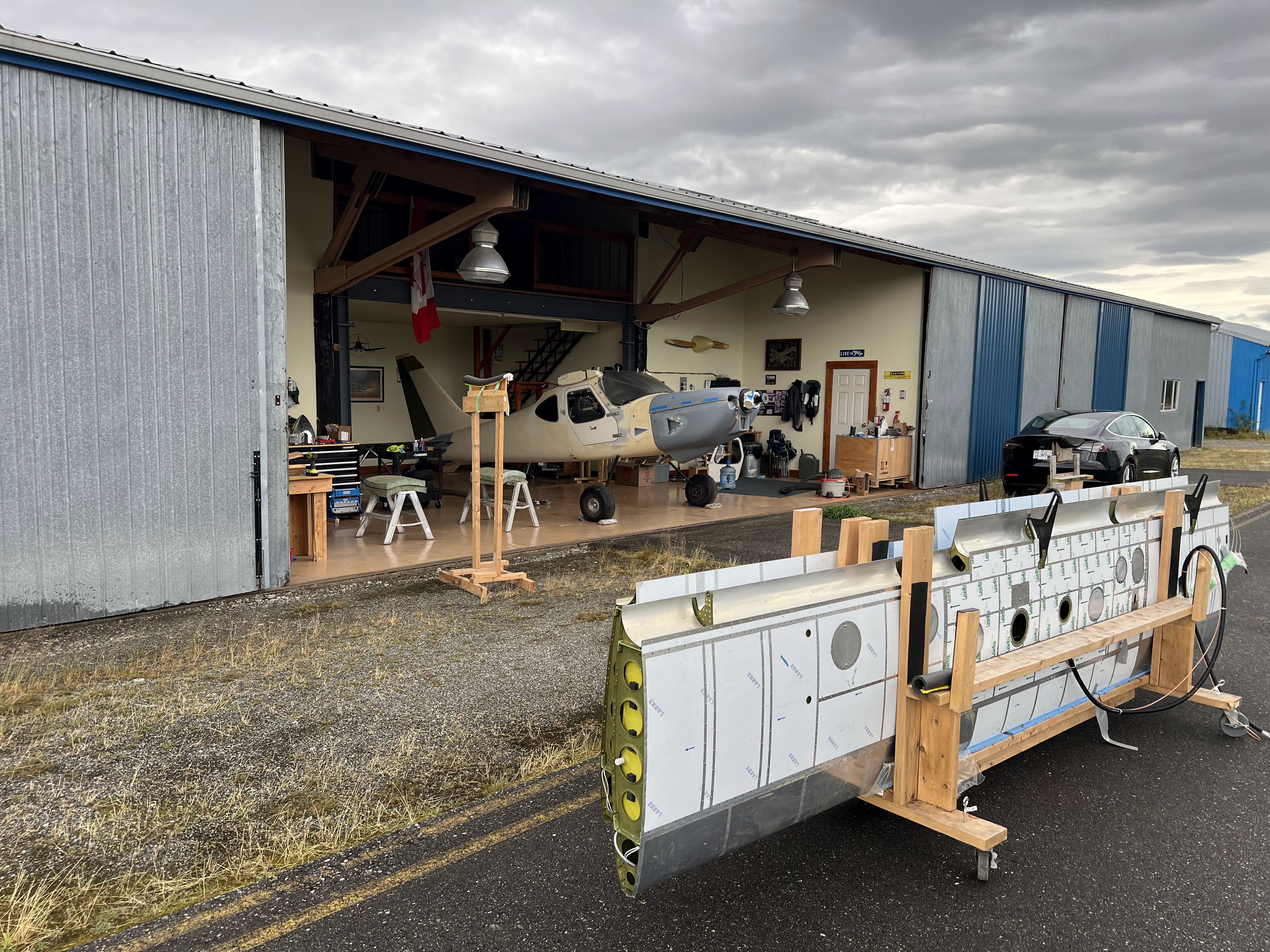
Exciting day... all of the airplane bits are now in the same location!


The fuselage has not been outside for well over a year.  You get a whole difference perspective when its not jammed in a small space...


The driver did a fantastic job of securing the fuselage for transport.  She bounced around a LOT during the drive, but stayed in place.  So grateful for that!


Safely in the hangar...


Saturday, 17 December 2022

Control Sticks

I am at that point in the build where progress is frustrating because I have overcomplicated a lot of things.  I decided to go with the Infinity Stick grips, and load up on functions on the grip itself.  They are a really good grip it a lot of ways.  Easy of installation and wiring is not one of them.

Well, thats not fair I guess.  The installation is fairly straight forward... but you have to trim 1" off the stick to get it to fit under the panel, drill a big hole for a plastic bushing, and a slot for the wiring to pass through.  But it nicely clamps onto the stick...

First things first... you need to set the fore / aft position of the stick.  That means you need uphostery (which I ordered) first, then the sticks have to be drilled to the yoke.  This is the part I have been avoiding because I was unsure how to tackle the issue.  Since I have the fuel lines installed, you have to work around them.

So today after (what seems like months) of indecision (and talking to other builders), I tore into it.  The holes have to be drilled through the yoke and stick, but I couldnt get my alignement jig on the yoke, so that means freehand drilling, which is prone to errors, plus you have to line up the sticks and I dont have the wings attached to center the ailerons.  But, there is some adustment on the yoke, and turnbuckles.  So I decided to just center the yoke with some wood blocks, center the sticks with a board (per the manual), and carry on bravely.


After marking 3/8" in from the yoke weldments, I drilled 3/32" pilot holes through the top only (yoke and stick) and clecoed them in.  That should hold everything in place.


I dont have the right length drill bit for the forward hole, but did for the aft (again, working around the fuel lines).  So both aft holes were drilled and a AN3-14 bolt dropped in replacing the cleco.


With the right length bolts I can proceed.


To the wiring.  UGH.

The infinity grip the following options:
  • 4 way hat switch
  • Trigger switch
  • Left and right thumb switches
  • Middle thumb switch
  • Pinky switch

After thinking a lot, and consulting the forum I decided on the following:
  1. 4 way hat switch:  Pitch and roll trim
  2. Trigger switch - Push to talk
  3. Left and right thumb switches - Left(a):  Autopilot disconnect / CWS.  Right(b):  Momentary toggle - forward, COM1 flip flop.  Aft - COM2 flip flop.
  4. Middle thumb switch - Audio panel swap from COM1 to COM2 and vice verse.
  5. Pinky switch - Transponder IDENT
That equates to a whole bunch of wires.  Items 1, 2, 3a are handled by the ACM wiring to the 'control stick' port.  Items 3b, 4, and 5 need to be wired directly.  The transponder IDENT will be handled through the ACM using a general purpose input.

Here is the wiring diagram for just the sticks.


This is not going to be fun.  10 lbs of poop in a 2 oz bag.

Grips mounted to the sticks after drilling.


Sticks fully drilled, ends cut and filed, grips mounted and wires fed through.


The Infinity Stick Grips are very nicely made, as assembled really well on top of the stick.  After about 15 disassembles / reassemblies I am reasonable good at it.  The issue is the wires... there are so many wires, and if they get caught in the channel for the stick, or against one of the bosses that the screws go through it wont go together.  If any little thing is wrong, you are taking it all apart again. If you want a grip that you just mount on the top of a stick, this is not the one for you.

Next is to connectorize the cables from the sticks and integrate in the ACM, Dynon Radio, Audio Panel, etc.  I thought I had enough connectors, pins and housings, but apparently not.  Ordered from Digikey today.

Connectorizing was not fun (I have an aversion to connectors anyway, specifically getting pins out of shells - never goes well).  There is a colour code for the wires, but there are duplicates.  For the most part, black is ground (but not always), and there are multiple red and blue wires.

  1. Sorted through all the wires and found the ground (using an ohm meter), and separated them from the pack
  2. Tied all the ground together on the stick side using solder sleeves.  There are 6 ground - so 3 into 1, then 2 into 1, then that wire went to the connector.  Sleeves are hidden under head shrink.
  3. Checked functionality of every switch at all points in the process.  Would really suck to get everything done and have a busted wire or bad ground.
  4. Connectorized the end using a d-sub 15.
  5. The connector will fit through, but without the shell, and it has to go through sideways.  I left enough bare wire to get it through.

Onto final wiring.  I have the ACM harness for each stick, but it doesnt come with IDENT, COM flip flops (x2) and Audio Panel swap.  These all have to be added to the harness.


So I cut open the pilot side harness, and added the 3 wires.  Oh what fun...

These 4 wires need to go to various places:
  • IDENT:  Goes to a PFD input on the AC Rear Connector
  • COM 1 SWAP:  Goes to the Dynon radio
  • COM 2 SWAP:  Will go to the yet to be purchased GARMIN NAV/COM
  • Audio Panel SWAP:  Goes directly to the Audio Panel.
I put everything together to test, and it all worked - except the Audio Panel COM SWAP.  It seemed like it would work every once in a while, but not like I expected.  I checked with both PS Engineering, and Advanced - but at the end of the day I just miswired it.  I had it connected to pin 21 on J2, when it should have been pin 20.  The issue was getting the connector apart on the audio panel without losing any hardware in the fuselage or panel.

To finally everything is done.  Sticks are wired, connectors attached, everything tested good.  Sticks are bolted in place.


Starting on the cleanup now.  It sure needs it.


Tuesday, 9 August 2022

Strakes

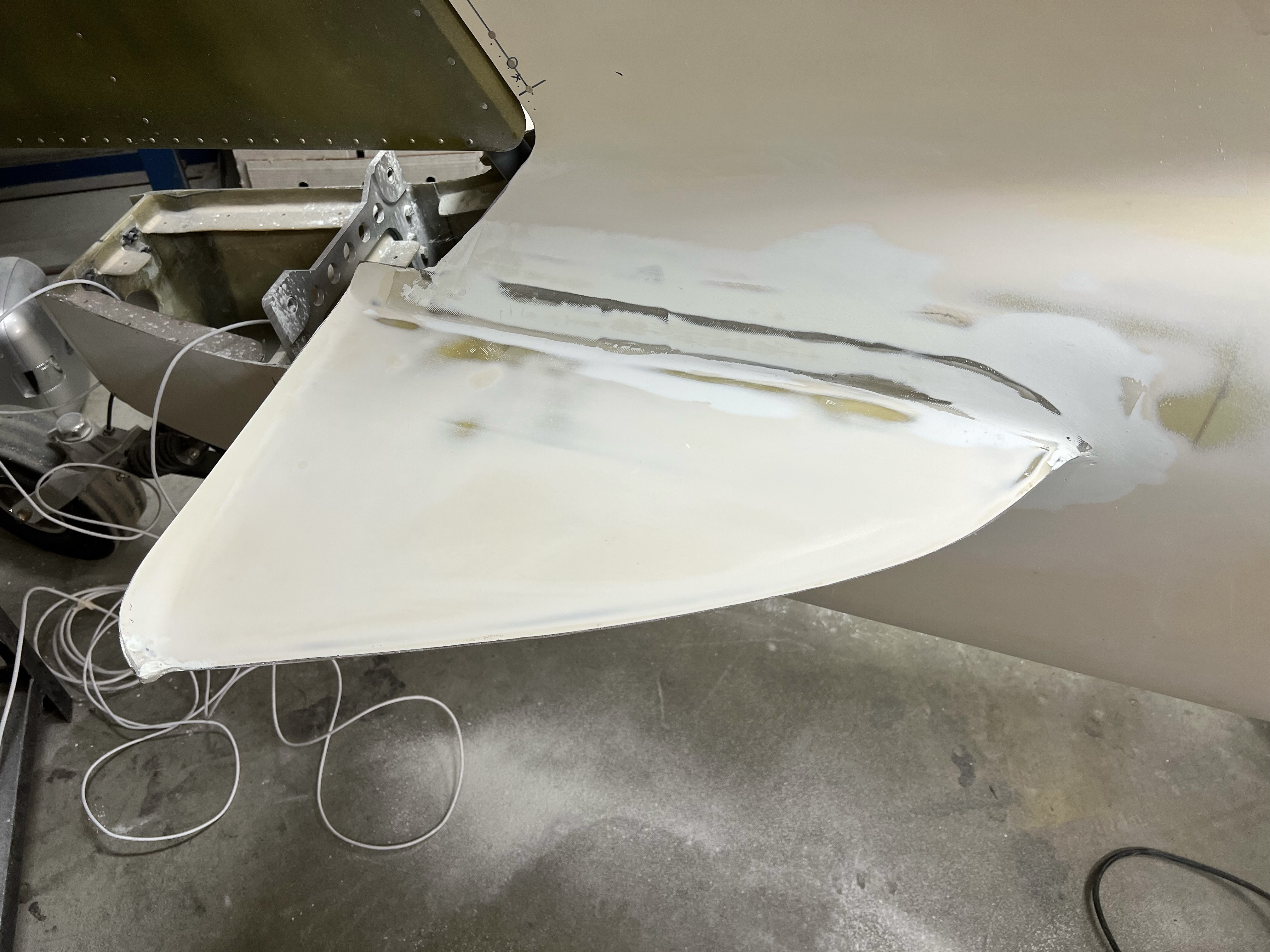
 The first builder that started the fuselage bonded the strakes on.  This involves bonding in the foam ribs, and the two halves of the strake, and then fitting the assembly to the fuselage.  My engine is inbound, so my goal is to finish up all of the messy / dusty stuff before it arrives if possible.

This picture is the strakes as they were when I bought the fuselage, but with a quick sand.


First layer of filler.  Just trying to fill the low spots.


Second later of filler.  Working on build the profile, plus the transition.


Third layer:  High build primer.  This way I can see what I have missed and refine the transition and any low spots.

Primer sanded...

2nd layer of high build


Multiple small imperfections still exist.  Putting this aside for now.  90 to 95% done.


Wednesday, 2 February 2022

Firewall - Part I

The partially completed fuselage kit I bought already had the firewall roughed out, along with all the brackets that tie the firewall to the fuselage.  Step 1 was to see how it fits...


Luckily, it fits very nicely :-)

Because I am not going with a 'standard' engine, I need to do a lot of stuff that is not in the book.  So I have been planning out where I am going to put everything.

Stuff to fit:

  • Batteries (including capacitors needed for UL install)
  • Voltage regulator (50A)
  • Gascolator
  • Fuel pumps / filters
  • Primary fuel feed / fuel injection return
  • Air / oil separator
  • Cabin heat box
  • Throttle, and cabin heat controls
  • Master relay(s) (do not need starter relay, as it is on the engine)
  • MAP sensor
  • Fuel pressure sensor (which is fitting to output of fine fuel filter, via banjo fitting)

In order to 'fit' everything, I had a local plexiglass shop make me a Plexiglas firewall.  They cut the outside profile of the firewall, and the slots that go around the nose gear mount.

I am not comfortable with the limited amount of hard points on the cage for attaching accessories.  So during this process, I am going to add a number of additional hard points.

My kit did not come with the material needed for the angle structure that goes on the firewall, so I ordered a bunch of 1.25 x 1.25 x 0.125 6061 T6 angle.

The Glasair documentation for anything firewall forward is very lacking... once I got over that and figured I am on my own, it started moving much quicker.  A lot of hunting and frustration was involved trying to figure out what to do.


Firewall Framework:  Glasair uses an aluminum angle structure (attached to hard points on the cage) to mount all accessories.  In a 'usual' Sportsman, this would include battery, oil cooler, engine transducers, firewall pass throughs for wiring, cabin heat box, etc.

Goal:  Have ZERO firewall penetrations that need to be removed.  Example:  Battery mounting - the goal will be to be able to remove the battery without having to remove a firewall penetration.  This will apply to everything.  Coils, fuel filters, regulator, etc.  Once the firewall and framework is mounted, nothing will need to be removed EVER.

With using a UL Power Engine, my needs are a bit different:
  1. (Electric) Fuel pumps (qty 2 - primary and backup, controlled by the ECU)
  2. Fuel filters (course and fine)
  3. Air / oil separator
  4. Gascolator
  5. Batteries (qty 2 - EarthX ETX900)
  6. Coil packs (qty 2)
  7. Master relays (qty 2 - one for each battery)
  8. Cabin heat box (stainless - Canadian requirement)
  9. Main fuel line (output from either pumps or header)
  10. Fuel injector return
Fuel Pumps / Fine Filters - Location (Note - also see Fuel System post for more details (add link)):  Option 1 will be to put the pumps on the forward tunnel inside the cockpit.  Option 2 is on the firewall.  Honestly, I don't like either option, but they have to go somewhere.  All of the hardware is ordered to adapt the standard UL pumps / filters to inline input and output rather than side entry.  With all this, it should fit in the tunnel.  If that doesn't work, then I will come back to putting all this stuff on the firewall.

I am pushing ahead with plan A - filters / pumps under the header, on top of the forward tunnel.  Something like this:


Tentative tank placement:


The firewall framework has been proceeding well.  Mounts made for coil packs, regulator, fuel filter, batteries, gascolator, etc.


Once the pump and filters are complete, then I can proceed to putting in the Plexiglas template and fitting the cabin heat box, cable passthroughs, air deflector, etc.  Hopefully then I can really start moving.

Plexi firewall in place.  Main fuel line drilled, as well as return.  Cabin heat airbox next.  Battery box clamped in place.


A lot of the above did not work out:
  • Battery box too wide and too low - hit engine mount (I finally had the brainwave I had better put it on and check for clearance issues...)
  • Gascolator not low enough.  Hit exit ramp that transitions between the bottom of the fuselage and firewall.
So I changed my mind on the battery box.  Decided to go stainless, and cover it in a reflective mat.  From reading on the forum, this seems to be a good option.  I will also put a 1" cooling flange on the front.

Redesigned the gascolator mount to be similar to the Glasair design (I am using the same Gascolator they use).


5 pieces to the battery box.  
  1. Floor the rivets from the bottom
  2. Back mount that will tie into the firewall structure on both sides.
  3. Front cover that wraps around to tie the back mount and floor together
  4. Strap that hold the batteries in.
To pull the batteries will require taking the box off, but it will only be 5 bolts (plus the wires) and the entire box comes out.

Firewall frame below removed for drilling / finishing.  The back is flush riveted so it won't interfere with the firewall.


Firewall frame all primed, relays temporarily mounted, gasolator fit checked, cabin heat box drilled.


Parts getting their grey coating to match the engine mount (and everything else)


Exit air ramp drilled.  The bottom is held in with captive fasteners on the bottom of the firewall stainless.  Screws will go through the fiberglass, air ramp, and then into the firewall structure.


Everything completed to date installed.  (New) plan is to finish all the cockpit / avionics wiring with the firewall out.  Real firewall will not be installed until after engine / engine mount has been test fit.

The firewall template has been out of the fuselage for a month or more while working on other things.  Its pretty much going to stay in this state until I have an engine.  Part II will cover the next phase of the firewall later in 2022.

Sunday, 2 January 2022

Header Tank

 A lot of this is covered in the 'Fuel System' post, but there are some additional details on the header tank - specifically the systems that measure fuel level in this post.

From a mounting perspective, the header is mounted on the forward tunnel just aft of the firewall.  Tabs have been welded on the top of the tunnel truss with captive fasteners (#10) in 4 places.

I mocked it up in wood to begin with to figure out the overall fit.


The pumps and filter fit under the header.

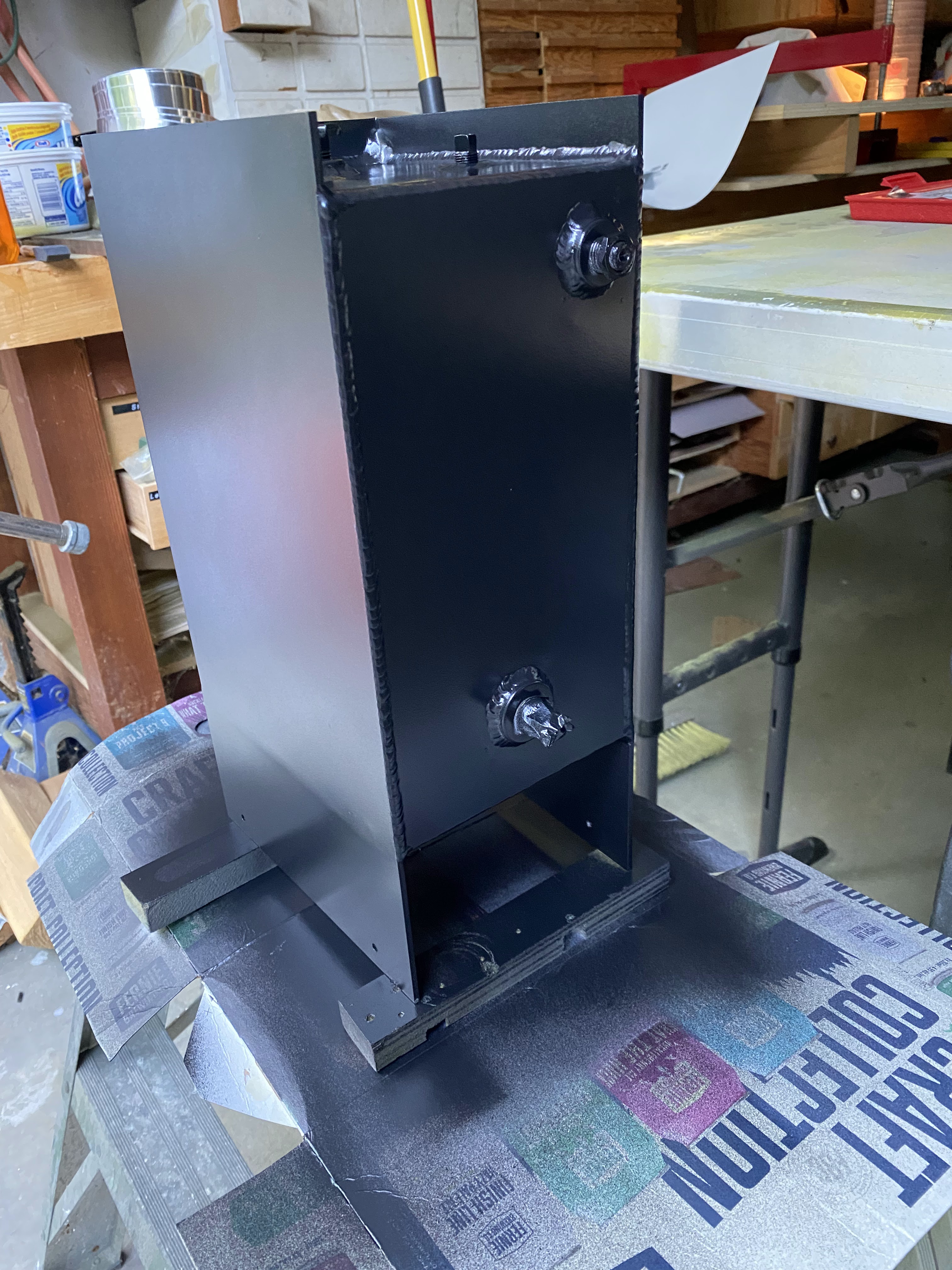
A friend of mine got the header made.  He had a shop bend the aluminum, and then he welded up the header.


Post tab welding


After finishing (tank was treated with Alumiprep and Anodyne, then primed, then painted).


My big concern with a header was knowing how much fuel is in it, and more importantly when it gets low on fuel.

In my panel design, my original plan was to have a capacitive probe in the tank to know how much fuel is in it.  Unfortunately, Advanced only supports 4 tanks (and I have 5 - 2 mains, 2 aux, and 1 header).  So I needed another solution.

Enter Radiant Instruments.  They have a number of innovative fuel probes.  My issue was I did not have room for a fuel gauge, so I decided to use fuel level senders (that basically say there is fuel at a given level, or not) with their LED indicator.  The indicator says "there is fuel, or there is not fuel".  2 of these mounted on the tank will tell me if I ever get the header too low.

So now the discussion goes to where to place them, which leads to fuel flow, header capacity, and time between warnings.

Current workbook with calculations:


Current sensor locations and indicator mess.


Bottom line(s):

  • From my calculations, the fuel system can deliver 63 GPH to the header.
  • At full power, the engine should draw about 22 GPH
  • If you get the initial low fuel indication on the header (which is right in front of the pilot), you have 1.66 minutes to correct.
  • When the 2nd sensor shows low, you have 1.44 minutes to correct.
  • The header has fuel for 4 minutes at full engine power (220 HP)
These are all calculations at this point.  Proof will come on the first flight.  But, based on these numbers you should NEVER see a low fuel indication on the header... ever.  Famous last words...


Panel header fuel level indication above the pilot side display.  Very simple.  Green = good, Red (flashing) = Bad.

Header tank in place with lock on the shutoff valve.  Also doubles as a mount for vertical fuel line.


So after a lot of messing around (and many months), it is finally in its (hopefully) finished configuration.  All fasteners are installed.  The only thing left to do is wire the fuel pumps, which I may do today assuming I have all the stuff.


Now it is onto the vent lines...