Search This Blog

Showing posts with label Avionics. Show all posts

Monday, 10 March 2025

Advanced Flight Systems - v17 software, and UL Manifold Air Temperature readout

I am excited... like really excited.

Advanced has released v17 software.  I have it loaded on a stick and ready to go (well two sticks, one for each display).

v17 provides support for Airmate charts and maps.  This is so incredibly cool.  Why do you ask?  Well I am glad you did...

The problem with Advanced is they only provided support for Jeppesen and Seattle Avionics charts.  Jeppesen is super expensive, and Seattle Avionics does not support Canada.  Seattle Avionics were threatening to support Canadian charts, but it never happened.

Airmate supports Canada.  In fact, I helped a friend install Airmate charts on his Dynon Skyview classic a couple weeks ago.

The next challenge is the UL Manifold Air Temp (MAT) gauge.  For the turbo engine, UL repurposed a canbus value for the MAT, as it is needed for the turbo engine.  This gauge will tell me how the intercooler is working, so its pretty damn important.  Ideally the inlet air temp needs to be less than 65 degrees C.

UL informed Advanced of the issue... some how it was missed, or forgotten, or omitted.  I dont know which, and at this point I really dont care.  I have been asking UL regularily when this will be available, and the answer was always soon.  But in fairness, I was not ready to use it yet.  Now I am.

v17 was their priority, and said they would get to it soon.  I receive an email today (Jan 29) that some if not all the support may already be present!  Dynon supports it on the EMS, and in their core code that Advanced uses.  So its down to display... and that may already be there as well.  They want me to test it and advise.... I'm on it!  That is the goal for today (one of the goals...).

Next piece of coolness... Advanced is going to support the AV-30 ADAHRS data as a backup to the main ADAHRS.  This means that I will have 2 ADAHRS, and that was the last piece I needed for a fully IFR capable panel.  I asked what wiring changes are needed, and the answer is... NONE!  Bada bing, bada boom.  This is down the road a bit...

Also need to check on the go around button, and the remote ident button for the Tailbeacon X.

All of this stuff is REALLY COOL.  Canadian maps, MAT support, 2x ADAHRS... that ticks a bunch of items off my list...

Updated to v17 last evening, and the MAT works!


Also remembered to additional features I am looking for from Advanced...

1. TOGA functionality.  I already have a button wired.

2. Remote IDENT for the TailbeaconX.

Sunday, 16 February 2025

More Progress... some frustrating, some not...

Well, the progress keeps coming... slowly.

Loaded all the UL520T parameters into the EFIS today.  Not hard.

Downloaded the checklist file... that will be left for cold days to come.  The checklist will be interesting... looking forward to that.

Brake leak appears to be fixed... but ANOTHER fuel leak.  Traced it to the fuel selector.  Everything cleaned, now waiting to see if it reappears.  I fixed it late morning, and there was nothing by dinner time... 

Lots of visitors today... lots of airplane talk.

Then I decided to tackle the hatch covers.  Watching the videos, those just need to get done.  I have had a mental block on these... I started fitting the port side cover ages ago, became frustrated and left them.  More frustration today... they just do not want to fit nicely.  Call to Zach in order for tomorrow morning.

Looking at the forum, this sounds like a common issue...


Wednesday, 28 December 2022

Advanced Deck, Foreflight and Wifi

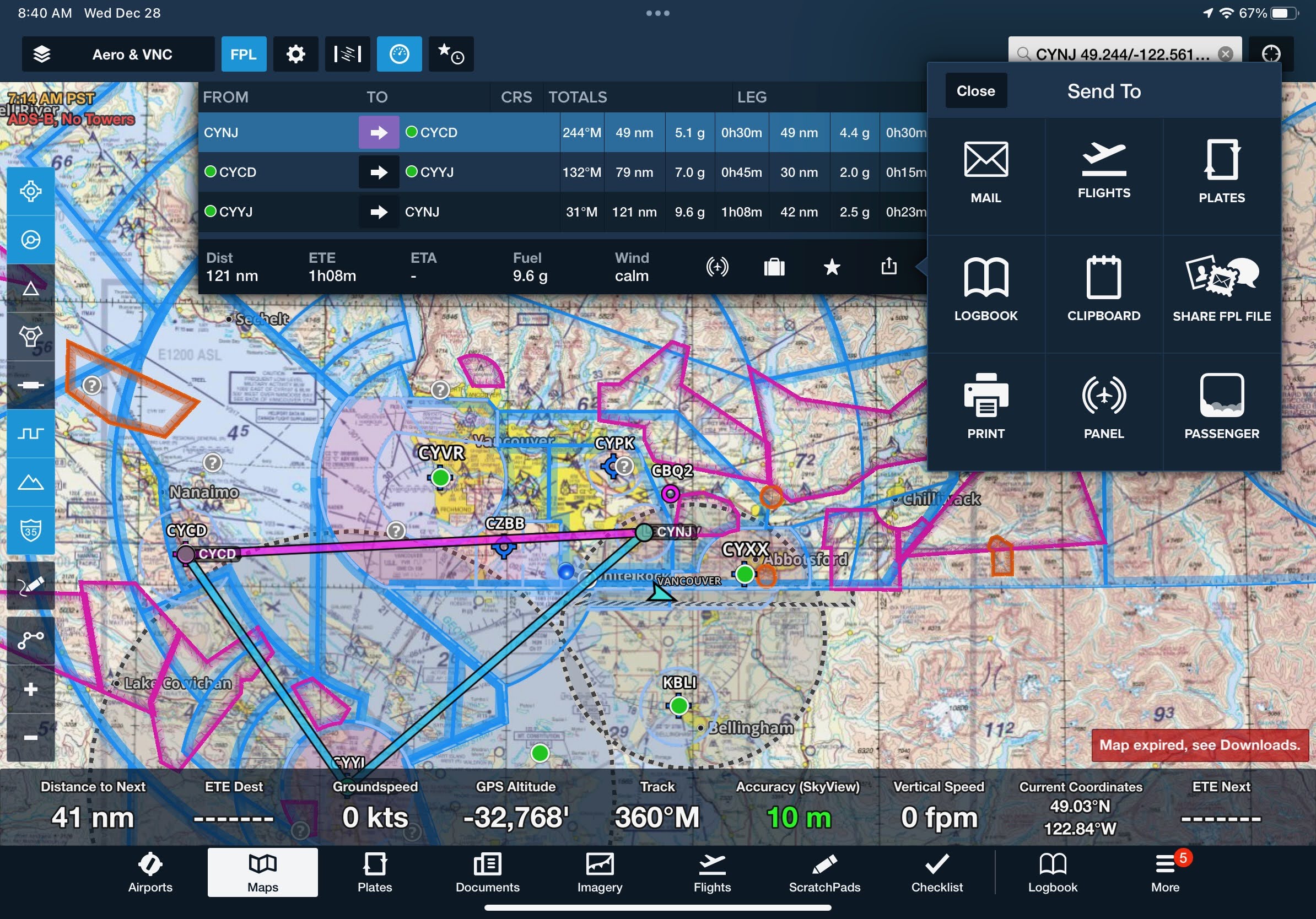
I purchased the Dynon wifi adapter as part of my avionics package, but had not getting around to plugging it in (that is pretty much all that is required from a physical standpoint).  So needing a motivation, I plugged it in.  The setup is easy... give it an SSID and password, and thats it.

I joined the network from my phone and opened Foreflight.


Well thats cool.

So I did up a basic flightplan on my ipad, connected it to the aircraft wifi, and the option shows up under 'Send to', 'Panel'.


The panel then wants you to confirm that you actually want to load it.


Piece of cake.

When airliners fly over, I get their ADSB feed in the shop.  Now I get it on both my ipad, and Advanced displays.


The only thing that is not working is my aircraft GPS.  There is a foil lining under our tile roof, so there is no GPS connectivity in the shop, so the altitude on foreflight is showing -32000 ft.

Friday, 23 December 2022

Wiring / Cleanup

I have been working on cleaning up the wiring mess I created for myself.  I call it 10 lbs of poop in a 2 lb bag.  But realistically, if you add up the weight of all the avionics and wiring its probably closer to 30 lbs all in.  Not that I have weighed it.

Having a super light engine, my plan was to move as much forward as possible to help offset the weight.  Between the panel and the firewall are the following components:

  • 2X 10.3" displays
  • Backup EFIS
  • Prop controller
  • Advanced ACM
  • UL ECU, boost controller and aux box
  • COM radio
  • Room for IFR GPS and NAV/COM
  • Avionics backup battery
  • Header tank
  • Audio panel
  • EMS
  • ADSB receiver
  • Hall effect sensor
  • GPS 2020 receiver
  • Skyview expansion bus
  • And all the normal 'stuff'.
Add all that together, and its 10 lbs of poop in a 2 lb bag.

Top down view of the mayhem...


The relatively clean panel hides the mayhem that hides behind it.

The GOOD news is everything works.  All the avionics are connected, the ECU is talking to the EMS, all the controls on the sticks do what they are supposed to.  Radio / audio panel / audio all works.  Servos are talking to the system.  Prop controller has power and just needs connection to the hub.  All of the lights (nav, strobes, taxi, landing, panel, overhead) all work.  Pitot heat is ready to go once the wings are attached and wiring finished.  ECU indicator lights.  Circuits for the engine and transfer pumps.  It all works.  Yay me.

It's not 'pretty' like I hoped it would be.  But to move the weight forward and contain it all between the panel and firewall is an extreme challenge.  If I could get rid of the ACM and use CANbus only, it would be way neater - but that is not the path I chose.

Once the weather dries out a bit, the engine will come off and the real firewall will go in, and then I can finish up the firewall forward wiring (fuel pumps, batteries, relays, shunt sense wires, prop controller, etc)

I am tired of wiring, and look forward to building parts again (which is totally ironic).

Merry Christmas.

Thursday, 22 December 2022

Update...

Progress is being made... albeit slowly.

The wiring on the 'Longnose' Sportsman is pretty much done.  The last bits remaining:

  1. Wire fuel pumps from the switch to the pumps.
  2. Alternate air switch / panel indicator
  3. EarthX battery fault wires
  4. UL regulator to main bus
And thats pretty much it.  Everything else is installed, wired an functions as expected.

I have the next 1.5 weeks on vacation, and have a few goals to accomplish:

  1. Clean up the rats nest of wiring.  OK, its not THAT bad, but needs some TLC
  2. Finish the last of the firewall penetrations and determine routing for the prop controller to prop cable, EGT's/CHT's, cabin heat cable, fuel injection return, boost controller lines, and thats about it (as if that's not enough LOL).
  3. Pull the engine and put it back in the crate
  4. Drill the 'real' firewall
  5. Rivet the flanges on the real firewall
  6. Adhere the firewall blanket
  7. Install the firewall and rivet it in place.
  8. Rehang all the firewall components (regulator, coils, fuel pumps, relays, batteries, etc)
  9. Reinstall the engine
Is all that doable?  Maybe - we will see.  I think I can get 1 through 7 done before January 2nd, maybe more.  But you have to have goals, right?

IF I can get all of the above done, then its onto engine / firewall forward 'stuff':
  1. Oil cooler mount and lines
  2. Oil cooler opening in the front of the cowl
  3. Intercooler mounting
  4. Ducting for the intercooler
  5. Air intake and filter mounting / plumbing
  6. Alternate air inlet
  7. Finish the exit air ramp on bottom of cowl
  8. Cowl 'finishing'
  9. Cowl fasteners
  10. Windows (front, top deck, doors (x3), fuselage) - the front window will be last (and probably just temp bonded until after first engine run)
  11. Brake lines from park brake valve to calipers
  12. Throttle and engine throttle (capture) bracket
Once all that is done, its off to the airport.  Hoping for mid 2023, then its onto final wing integration (wiring, fuel lines, hatch covers, wing tips, lights) and final wiring, etc for the tail.

80% done, 80% to go.  Will be finished on Tuesday.  Just not saying which Tuesday... 

Saturday, 17 December 2022

Control Sticks

I am at that point in the build where progress is frustrating because I have overcomplicated a lot of things.  I decided to go with the Infinity Stick grips, and load up on functions on the grip itself.  They are a really good grip it a lot of ways.  Easy of installation and wiring is not one of them.

Well, thats not fair I guess.  The installation is fairly straight forward... but you have to trim 1" off the stick to get it to fit under the panel, drill a big hole for a plastic bushing, and a slot for the wiring to pass through.  But it nicely clamps onto the stick...

First things first... you need to set the fore / aft position of the stick.  That means you need uphostery (which I ordered) first, then the sticks have to be drilled to the yoke.  This is the part I have been avoiding because I was unsure how to tackle the issue.  Since I have the fuel lines installed, you have to work around them.

So today after (what seems like months) of indecision (and talking to other builders), I tore into it.  The holes have to be drilled through the yoke and stick, but I couldnt get my alignement jig on the yoke, so that means freehand drilling, which is prone to errors, plus you have to line up the sticks and I dont have the wings attached to center the ailerons.  But, there is some adustment on the yoke, and turnbuckles.  So I decided to just center the yoke with some wood blocks, center the sticks with a board (per the manual), and carry on bravely.


After marking 3/8" in from the yoke weldments, I drilled 3/32" pilot holes through the top only (yoke and stick) and clecoed them in.  That should hold everything in place.


I dont have the right length drill bit for the forward hole, but did for the aft (again, working around the fuel lines).  So both aft holes were drilled and a AN3-14 bolt dropped in replacing the cleco.


With the right length bolts I can proceed.


To the wiring.  UGH.

The infinity grip the following options:
  • 4 way hat switch
  • Trigger switch
  • Left and right thumb switches
  • Middle thumb switch
  • Pinky switch

After thinking a lot, and consulting the forum I decided on the following:
  1. 4 way hat switch:  Pitch and roll trim
  2. Trigger switch - Push to talk
  3. Left and right thumb switches - Left(a):  Autopilot disconnect / CWS.  Right(b):  Momentary toggle - forward, COM1 flip flop.  Aft - COM2 flip flop.
  4. Middle thumb switch - Audio panel swap from COM1 to COM2 and vice verse.
  5. Pinky switch - Transponder IDENT
That equates to a whole bunch of wires.  Items 1, 2, 3a are handled by the ACM wiring to the 'control stick' port.  Items 3b, 4, and 5 need to be wired directly.  The transponder IDENT will be handled through the ACM using a general purpose input.

Here is the wiring diagram for just the sticks.


This is not going to be fun.  10 lbs of poop in a 2 oz bag.

Grips mounted to the sticks after drilling.


Sticks fully drilled, ends cut and filed, grips mounted and wires fed through.


The Infinity Stick Grips are very nicely made, as assembled really well on top of the stick.  After about 15 disassembles / reassemblies I am reasonable good at it.  The issue is the wires... there are so many wires, and if they get caught in the channel for the stick, or against one of the bosses that the screws go through it wont go together.  If any little thing is wrong, you are taking it all apart again. If you want a grip that you just mount on the top of a stick, this is not the one for you.

Next is to connectorize the cables from the sticks and integrate in the ACM, Dynon Radio, Audio Panel, etc.  I thought I had enough connectors, pins and housings, but apparently not.  Ordered from Digikey today.

Connectorizing was not fun (I have an aversion to connectors anyway, specifically getting pins out of shells - never goes well).  There is a colour code for the wires, but there are duplicates.  For the most part, black is ground (but not always), and there are multiple red and blue wires.

  1. Sorted through all the wires and found the ground (using an ohm meter), and separated them from the pack
  2. Tied all the ground together on the stick side using solder sleeves.  There are 6 ground - so 3 into 1, then 2 into 1, then that wire went to the connector.  Sleeves are hidden under head shrink.
  3. Checked functionality of every switch at all points in the process.  Would really suck to get everything done and have a busted wire or bad ground.
  4. Connectorized the end using a d-sub 15.
  5. The connector will fit through, but without the shell, and it has to go through sideways.  I left enough bare wire to get it through.

Onto final wiring.  I have the ACM harness for each stick, but it doesnt come with IDENT, COM flip flops (x2) and Audio Panel swap.  These all have to be added to the harness.


So I cut open the pilot side harness, and added the 3 wires.  Oh what fun...

These 4 wires need to go to various places:
  • IDENT:  Goes to a PFD input on the AC Rear Connector
  • COM 1 SWAP:  Goes to the Dynon radio
  • COM 2 SWAP:  Will go to the yet to be purchased GARMIN NAV/COM
  • Audio Panel SWAP:  Goes directly to the Audio Panel.
I put everything together to test, and it all worked - except the Audio Panel COM SWAP.  It seemed like it would work every once in a while, but not like I expected.  I checked with both PS Engineering, and Advanced - but at the end of the day I just miswired it.  I had it connected to pin 21 on J2, when it should have been pin 20.  The issue was getting the connector apart on the audio panel without losing any hardware in the fuselage or panel.

To finally everything is done.  Sticks are wired, connectors attached, everything tested good.  Sticks are bolted in place.


Starting on the cleanup now.  It sure needs it.


Wednesday, 14 December 2022

BNC Connectors

I have an aversion to all connectors.  They always seem to make my life hard, and I mess things up and cannot get them apart.  The top of the list has been BNC connectors, because I didnt understand them.

A buddy of mine showed me how to put on a BNC, and still I messed them up.  You have to strip 3 times - center conductor, inner jacket, outer jacket - I get that - but how long does each of them need to be?

I have 3 types of connectors for the Sportsman

  • BNC Male
  • BNC Female Bulkhead
  • TNC Male

I found it extremely hard to find the correct assembly instructions for each type of cable.  After searching, I found it for the Amphenol BNC male and TNC Male, but not the BNC Female Bulkhead.

So I measured everything and mapped it out (BNC Female Bulkhead).


Dimensions are available if you have the part number.  Below is the Amphenol TNC male.


This may be 'old hat' to some, but i was just inexperienced - and after wrecking some pins I thought there has to be a better way.  Now I can do a BNC and not waste any parts.

Happy days.


Tuesday, 6 December 2022

CANbus / UL Power Integration

Finally got around to wiring the Dynon EMS-221 to the UL ECU.

The Dynon manual does not give a lot of detail, except the pinouts - and there are omissions.

Here is what came with the engine and harness:


On the EMS side, the manual gives some info on UL Power installations, but it is not overly helpful.  However, I asked Advanced specific questions about the ground wire, 120 ohm resistor, and shield from the UL side.  Below is what I got back.


This is what I followed.  I added the termination resistor (however, Advanced noted that they probably have many Rotax installs in the field with no resistor, and no issues), ground, and tied the shield to the EMS ground.

When I fired everything up, there was no obvious was to see the CAN bus status.  I poked around forever and nothing was obvious.  I had a 2AM brainwave that I needed to change the engine selection.  My PFD was set to '6 cylinder turbo', when it should have been 'UL 6 cylinder turbo'.  As soon as I changed that, I now had the option to select CANbus inputs for the different gauges and I could see that CANbus was connected and working.


As you can see, there is an OIL PRESSURE A and OIL PRESSURE B - where A is valid, and B is not.  I assume B is for if you have a 2nd ECU.  Confirmed on 12/6/2022 that the 'B' lane is for a 2nd ECU..

Everything appears to be working.  I have to set the limits on everything still, but that can wait until closer to first engine start.


Wednesday, 30 November 2022

UL Power - ECU Wiring

I thought the UL ECU wiring would be simple, and in some ways it is simple.  But as always, the devil is in the details.

Power:  The ECU has 6 wires that all need to be attached to an ECU switch.

Ground:  The ECU has 5 wires that go to ground.

FPCR (Fuel Pump Control Relay(s)):  The ECU can control the pump(s).  I opted to do so, but there is a 2nd bypass circuit around the relays just in case.

Ignition:  Circuits for left / right or 1/2 coils to switches (or a standard key switch).  Grounded they are OFF, open they are ON - just like a mag.

Aux box:  Provides ambient pressure.  Plus other things, but this is all I am using it for.

Boost controller:  Control line from the ECU to the Boost Controller, plus power and ground.

CAN-bus:  Data lines to grab engine data via CAN.

RS-232:  Separate RS-232 connection for an EFIS feed, or to use the UL-READ software.  I need to order this cable.

Discrete engine inputs:  Separate inputs for Engine RPM and fuel consumption.  I am not using these, as they are provided over the CAN-bus.

Dummy lights:  2 LED's.  1 for 'check engine' (which indicates a sensor fault), and 1 for 'low battery'.  I planned for both of these in the panel.  The ECU only provides a ground to activate these LED's, power is separate.

The above is the basic lay of the land.

Current schematic below.


At present, everything is wired except the key switch.

The challenges:

  • The ECU is mounted on a tray forward of the instrument panel.  If it needs to be removed, take out the MFD, remove the two harnesses, loosen the bolts and its free.  You should be able to do all this sitting upright in the seat.
  • Making the above happen is a challenge.  I had to route all the wires in two consistent bundles (one firewall forward, and one for the cockpit interconnects) and not running in 4 different directions.
  • To do so, I fabricated some wiring 'braces' that everything is tie wrapped to.  But its all very condensed. Hopefully this works out.
Progress:
  • Everything is wired for the ECU, and it powers up (the LED's flash upon startup).
  • The next big step is to see if the ECU connects to the CANBUS on the EMS221.
  • The wires are not in their final position.  I want to make sure everything works before doing the final tie wraps (hence no pictures, it looks pretty ugly right now)
What's left to wire:
  • Magnetometer:  Cable is run, but needs to be shortened (ordered it too long)
  • Fuel tank probes.  Wires to the EMS, needs to head out to the wings.
  • Sticks:  Sticks themselves are wired, just need to route them and connectorize from the ACM (plus the pull downs from the audio panel, com, and ACM aircraft rear connector
  • RF / antennas:  VOR, 2xCOM antennas.

Probably forgetting something, but its almost there.


TO/GA Button

I had figured I would eventually figure out where to wire the TO/GA button (Take Off / Go Around).  That never happened, so I needed to ask Advanced.  Well, that feature is not available yet - coming in release 17 (current release is 16), with no planned delivery date that they would commit to.  Well I am not ready to fly yet, so no big deal.

The button needs to be wired to one of the PFD inputs on the Aircraft Rear connector:

From the Advanced Manual:

Will use PFD2, pin 14.

I was really nervous about opening up my AC Rear harness, but of course it was a non issue and took 2 minutes.


Last step is testing it, but that will have to wait until the displays are back in.


Dynon EMS-221 Wiring

As Advanced Flight Systems is part of Dynon, it stands to reason that Advanced would use the Dynon EMS (Engine Monitoring System) unit.  Dynon has 2 flavors - the EMS 220, which is the standard unit - and the EMS 221, which has CAN-bus connectivity.  I need the 221.

The EMS-221 has 3 connectors:

  1. DB9 for the Skyview Network connection
  2. DB37 for all of the engine wiring (except CHT and EGT)
  3. DB25 for CHT and EGT probes
1 and 3 are straightforward.  2 is interesting.

The UL ECU passes most of the engine data over the CAN-bus connection.  From the UL manual...


Bottom line:  There is very little for the EMS-221 to do, other than getting the CAN-bus data from the ECU.  Here is the pinout (only yellow items are planned to be used)


Basically current, voltage, fuel tanks, and CAN-bus.  I have a question into Advanced on whether or not I can use the 2 voltage pins, as these are on the ACM as well - so these might not be needed).


Everything is wired, except for the tank sensors.  Kinda need the wings for those...

I put the EMS on the bottom of the right hand avionics tray, thinking this would be easy to get to. Yeah, right.  Its not impossible, but definitely not easy.  Removing the ECU makes it easier.

Fuse Panel

I have a couple circuits that I dont want to run through the ACM.  Why you ask?  Well, what if it fails.  Or, what if the current draw is high and the function is not essential?  

Things that are going to be fused and not through the breaker panel or ACM:

  1. LED indicators.  2 for the UL ECU (Check Engine and Low Battery - the ECU does not provide power for these, only a ground to activate them).  Plus another for the Alternate Air Inlet on the airbox.  Dont need carb heat as the engine is injected, but need an 'emergency' air source if the filter gets iced up.  1A circuit
  2. Header tank warning lights.  If the ECU dies, I want these alive and functional.  Another 1A circuit
  3. Seat lumbar support.  It has a small pump and inflates/deflates the bags in the seat.
  4. Seat heaters.  I am a wus.  I like seat heaters.  These draw more than the ACM has capacity for.
  5. Other stuff down the road.  Will be nice to have a place to get power that is somewhat readily accessible.  2 spare circuits.
I found a really nice automotive style 6 fuse panel that is small and light, and has indicator lights as to their health.


The plan is to mount it on the starboard side of the fuselage, just above the rudder pedals on the side of the fuselage.  The original plan was to make a plate and attach it to the cage tubes with adel clamps.  Well, I hate adel clamps, and mounting it up there with the bulk of the avionics installed would be a nightmare - so I decided to bond the bracket to the fuselage.

The bracket is a simple hat shape.  The tabs pick up the holes in the fuse panel, and the bulk of the bracket will be epoxied on.  The below pic is the bracket clecoed in place, ready for bonding.


Because its winter here, I need enough heat to get the resin to cure.  Luckily I have a big heater in the garage, but it will cost me.  The bracket has already been fit to the fuse panel so it should just screw in once cured.  I waited until a relatively warm day (aka 10 degrees C) to do this.

Done and first circuit wired (power for LED indicator lights and header warning lights).


Wednesday, 23 November 2022

Instrument Panel Redo (Carbon Shroud Only)

 It's a long and sad tale, but I had to replace my carbon panel with a new one.  Which meant cutting and fasteners all over again.  Carbon fiber is itchy... do not recommend cutting it and then going to bed.

The good news is everything is faster 2nd time around.  In 2 evenings I had everything cut and most of the fasteners installed.  I have to make new brackets for the nutplates on the switch plates, because of the switch plate dimensions, standard nutplates will show the rivets in the carbon.  Hopefully this too goes faster 2nd time around.


I am finally (almost) back to where I was in April (its now August).  Still missing a few fasteners that will need to be riveted in later.


I have been wiring like a madman for the past 2 days.  The aircraft front and aircraft rear ACM connectors are done.  The trim and flap connector is done on the ACM end, plus the aileron trim wing bulkhead connector.  There is still a ton of wiring to do.  Like days and days more.  Plus the engine wiring integration (which should be relatively easy... famous last words).

Everything is working as before, except I have added some wiring.

  • Autopilot servos:  Not working.  The ACM says they are drawing power, but the Skyview network cant see them.  Troubleshooting with Advanced. Fixed and working.  Factory harness was wired incorrectly, and I missed it.
  • Recognition light.  Working.
  • Wing wiring to bulkhead connectors.  Working
  • Glareshield fans.  
  • Overhead cabin light
  • Compass light
  • Aileron trim.  Not tested
  • Elevator trim.  Not tested
  • Flap position sensor.  Not tested (potentiometer not yet installed)

The last piece to mount is the magnetometer.  I dont know why, but I have been dreading this.  Used some foam / glass test pieces I had and just chopped them up.  Simple and light.  The below picture is bonded to the fuselage.  The aluminum bracket is just for placement and will be removed.


Tuesday, 22 November 2022

Flap Position Sensor

Ever done something that you know is (close to) useless, but do it anyway?  And spend way to many hours in the process?  Yeah, been there.

The Advanced system on the ACM flaps / trim connector has flaps, aileron and elevator trim - both motor drive and position sensors.  The Sportman has manual flaps, so no need for the motor - but I want the position sensor (which is stupid me thinks).  I had the sensor, so it was just a question of mounting and wiring.

I ran all the wires from the FLAPS-TRIM connector.  Aileron trim is run to the right wing connector.  Elevator trim bundle is curled up in the back of the fuselage, and the flap bundle was sitting in the middle.

The bracket for mounting the sensor is deceptively simple.  Mounting it (using 2 adel clamps) is the challenge to get everything to line up and have nothing touching.

If you are going to do this (don't), get the 1.2" sensor.  Where I mounted it needs about 1" of travel, and I set it for about 0.1" of slop on either end so its not bottoming out.  The 'arm' is just a piece of welding rod, bent.  Yeah, that took 3 goes to get a good one.

Cutting to the end... Flaps retracted


Flaps extended


Wired and labeled.  I used solder sleeves.  Don't know why, because I hate them.  But in this application they seemed like the right choice.  I didnt shrink wrap everything like I usually do because I know these will break at some point.


There is a loop in the cable for WHEN the STUPID 26 GA wires break, there is enough slack to resplice.


Monday, 14 November 2022

Prop Controller / Manual Pitch Change Switch

This entry is about a lesson learned, and creeping elegance.

When I layed out my panel, I put a spot in right above the throttle for the prop controller (which goes in a 2.5" standard hole).  What I FORGOT was the manual course / fine pitch switch needed for manual operation.

I dont have any room, and where I do have room it doesnt fit (too tall).  This is the wee beasty...


After much pondering, I decided under the throttle / instrument panel would work.  Its close to the throttle, out of the way, etc.  I could use 2 of the bolts the secure the panel to the cage to tie it in.

The first version was pretty crude and was not square.  The 2nd version was much better, but for some reason I decided the mount the switch on the face of the panel.  Once I realized that the mounting holes in the switch were threaded (6-32), I pitched that one and made a 3rd.

2nd version


3rd (and hopefully final) version


The ultimate position would be beside the controller, but I dont have room.  2nd best would be on the switch panel beside the throttle, but the switch is too tall for that.  The other consideration was to keep it away from peoples knees.  It is in the center of the airplane (lined up with the tunnel cover below).


Saturday, 29 October 2022

Schematics and Wiring

I have done a fair bit of wiring in my time.  I don't consider myself an expert, but it almost always works. Where I struggle is on making it look 'right'.  I want this one to be 'right'.

You need a wiring diagram - that is a must.  However, I am also building a wire run list in Microsoft Excel.  The two go hand in hand.

The wire run list show you extreme detail on each wire.  Where is it from, where does it go, what does it connect to, wire size, color, etc.  The schematic gives you most of those details.  The nice thing about excel is you can filter and search.

Below is an example of the autopilot servo wiring.


And here is the drawing from Advanced.

Note:  I do not have a yaw servo, but the ACM supports it.

Where the Advanced drawing is correct, I am simply using that.  No point reinventing the wheel.  However where it needs modification, I am drawing from scratch.

I looked around for quite awhile for a good schematic software.  The basic requirements:

  • Multi platform.  If I ever sell the plane, someone will need to be able to edit the drawings.
  • PDF output compatible (this is pretty universal)
  • Decent parts library
  • Easy to use.
  • Preferably free (or low cost)
  • Supported.  Did not want to find a piece of free software that goes away or is not supported in 5 years (as an example).

After lots of hunting and frustration, a fellow builder put me onto QElectroTech.  On a scale of 1 to 10, I give it about a 7.  It is by no means perfect - but its free, and does most things that you need.  It has a pretty good parts library, and you can make your own parts (what the software calls elements).  Its multi platform as well.  It does take a bit of getting used to.

Below is my main power distribution (not yet finished).

And my control stick wiring (this one is pretty much finished).


Bottom line:  The documentation is going to be a lot of work - especially making the 'elements' where needed.  But it is necessary and worthwhile.


Tuesday, 9 August 2022

Instrument Panel - Part III (Wiring)

Now the wiring begins.... I both love and dread this part.  Love it because it makes things work, and dread because compromises will need to be made.

Step 1:  Electrical bus(ses).

Target is 3:

1. ACM - which includes avionics, lights, pitot heat, etc.  Everything that the ACM powers, which is everything but engine.

2.  Engine bus.  Stand alone bus for the engine, using breakers.

3.  Everything else bus.  This will be fuses, and for things that dont really matter - like seat heaters.  This will be the last priority.

The output of the two batteries goes to a central point, which is the current shunt.  This shunt will measure the total input / output to the batteries and will be inclusive of everything.  From the shunt, power goes 3 ways - to the ACM, Engine Bus, and to a fuse panel.

Fuel Pumps

The UL Power ECU has the provision to 'control' the fuel pump (or pumps) via a relay.  The ECU drives the coil on the relay (Fuel Pump Control Relay - FPCR), so it can turn the pumps on or off.  This is useful when on the ground working on things.  The system will pressurize, then the pumps shut off.

However, what if the relay fails?  So my fuel pumps switches have an 'auto' position (which goes through the relays) and 'force', which does not go through the FPCR.  Overkill?  maybe.

Everything else engine needs to wait until it arrives - hopefully in late May.

From a wiring perspective... 2 power feeds from each of the pump breakers.  1 feed goes directly to the switch, one goes to the FPCR.  The center position of the switches goes to the pumps.  The pump wiring is on a connector as the whole fuel pump tray is removable (kinda - have to take the header tank out first).


Header tank sensors.

Well this has been fun.  The sensors I bought from Radiant are cool, and I tested them very thoroughly with water to ensure they do what they should do.  But their connectors are, lets say, interesting.

The sensor is connected with a USB cable.  The head unit (of which I have 2) has the power connections.  Plus the cable lengths were way too long.  So I shorted everything up and put them both on one connector.


They are temporarily wired to power off a breaker to verify the wiring and connector.  Debating whether to power them from the ACM or a breaker or fuse.  Probably the ACM long term.


They flash red when liquid is not present.  Obviously the tank is empty, which is a good sign.

Radient recommends siliconing the LED's into the holes.  Not sure if I am going to do that, or make a mount.


ACM and Pre-Built Harnesses

I love the ACM.  I love the harnesses.  I have to figure out how to tame them.

To start, I plugged everything in.  No wires are tied in anywhere.  Just wanted to get the lay of the land (so to speak).  Holy crap, its a lot of wires and I am nowhere near done yet.

Dont judge me based on these pics.  Please.


The plan is to figure out where everything will go, then take it all apart and finish the trays and brackets, then reassemble for good. But I have to build the aircraft front, rear, and wing harnesses.  Everything is ordered to do that.

Main Power Distribution

OK - this is a mess.  But you have to start somewhere.  Again, the purpose was to figure out what goes where.


Two EarthX ETX900 batteries, two master relays with flyback diodes.  Each battery can be switched in or out.  This is all pseudo temporary, but it works.

The output of the two relays is bridged together, and the starter will come off here.  From the bridge point, goes to the main shunt with 6 gauge wire.  From there, goes to the ACM and engine bus.  The battery, aircraft frame, and engine all tied to a single firewall ground point.  Also a 10 gauge wire to the avionics bay ground bus.  This may need to increase to 8 gauge.

Engine Bus

As the ACM shies away from anything 'engine' related, I decided to have breakers for everything engine and fuel related.


10 gauge wire coming from the main current shunt on the hot side of the firewall.  It passes through a Hall effect sensor, so I will know (in theory) the current draw of everything engine / fuel related (but I won't know what is drawing what - just the total).


The Hall effect sensor is mount under the starboard avionics tray.  This may have to move simply for serviceability.  It will be very difficult to change - if not impossible.  On 2nd thought, if the MFD is removed there is a clear shot to it, but all of the wiring is not yet installed so that may change.  Time will tell.

Harnesses to build

- Aircraft front:  Comprises of prop controller, taxi lights (which will go to the wings - but that is a different story), cabin lights, panel fans, belly strobe, elevator trim.

- Autopilot servos:  These are pre-built from Advanced, need to be terminated on servo end.

- Sticks and flaps:  PTT, AP disconnect, IDENT, flip flops, Audio Panel switch, flap position potentiometer

- Wings (aka Aircraft Rear):  Pitot heat, landing / taxi lights, nav / strobes, fuel transfer pumps

- Engine sensors:  EGT, CHT, Fuel Pressure, CANBUS (to ECU, which has a large number of sensors), fuel tank sensors, etc.

The panel has taken a bit of a back seat due to waiting for a new panel from Glasair.  Should be here August 9th, then I have to recut it all over again.