Search This Blog

Showing posts with label Upgrades. Show all posts

Friday, 14 January 2022

Baggage floor

 I want a 4 person airplane... well, kinda.  I want the ability to take 4 people (even 3 will do).  Basically more than 2.  BUT, I want the ability to take stuff.  Stuff like camp gear, folding bike, suit cases, etc.  My sportsman will be a traveling machine, whether that is to go up north, or just see the country.  I want flexibility.

So that means I need rear seats, and some kind of floor.  Originally I was contemplating mounts that I could strap stuff down to the floor (which is the inner skin of the fuselage), but its not flat.  That would be a constant pain.

Well, a fellow Sportsman owner put a pic of his solution on the Glasair Forum.  

Take out the rear seat bottoms, and then the baggage floor is two pieces.  The aft piece from the seat bulkhead to bulkhead A is fixed.  The forward piece from the seat bulkhead to the seat back is hinged.

Zach Chase (Fibertech Composites) builds the rear floors.  You give him the dimensions, and he makes it slightly larger, and you cut to fit.

I sketched out the dimensions, and sent to Zach


Here are the two pieces provided by Zach.


The pieces are fiberglass (not carbon) with blank pigment resin.  Looks cool.

Because they are to big, I need to cut them down.  This will NOT be the fun part.

I recreated my original dimensions on the floor by first marking the centre line and working out.  The tape is so I can see the lines.


The cuts were actually a non event.  I weighed the floor down with weights when cutting so there was more restriction against the table saw.

Worked out well.  I should have extended the lines to account for the curve in the fuselage, which would have been close to 1/4".  But it now is what it is.  Can't change it.


Next step is to account for the fasteners that sit under the floor, and to make a small depression around them.  There are two on the forward bulkhead, and 4 on the aft foot rests.  The kids are too old, we no longer have any play-dough.  But I figure plumbers putty will work, but its cold in the shop and it needs to warm up a bit.  That will be a tomorrow project.

I created two tabs on each side forward that are tied into the bulkhead and the fuselage.  They started off as a 4 layer layup on a flat surface, then bonded to the underside of the bulkhead (clecoed in place) and the fuselage.  Once cured, two more layers of glass on top and bottom.  I don't think they are going anywhere.

For the aft mounts, when I made the footrests, I tied them into the centre tunnel, bulkhead A, and the floor (very similar to how Glasair does it) - but I made them a bit deeper horizontally (2").  That should give me a good surface to mount the aft portion of the floor.

I have bought a rivnut tool, and a bunch of rivnuts.  A whole new tool to play with.

Floor attached to the fuselage in 4 places.  Probably needs 2 more mid-span.

Rear floor bolted in place.


First cut to get the forward portion of the floor to fit.


For the hinges, after consulting with Zach I took out the foam around the hinges, with the intent to fill with a mixture of resin, cabosil and q-cell.  My plan is to mask off everything, support the floor upright, wax the clecos, and pour the mixture in and let it set (and hope nothing leaks).  This should really stiffen up the front around the hinges.  Without the foam, the fiberglass top is REALLY flimsy.

I still need to trim a little more off the forward portion of the floor, but am going to wait until after the hinges are reinforced so everything is nice and still.  The hinges are all drilled on the floor portion.

Forward portion of the floor with the foam cut out, hinges in place, and filled with resin / q-cell / cabosil.


This one is done, except that I need a few more rivets to finish the hinges, and the hinged section needs a bit of sanding as its rubbing slightly on the left side.  Oh, and a bit of touch up paint work is needed where the tabs were bonded.


Monday, 10 January 2022

Front Seat Pans (and Seat Pan Inserts)


 The front seat pans are a fiberglass tub that sits in the tubular steel cage, and gives the upholstered seat bottom somewhere to sit.

The issue with the standard seat pans is removal for annual inspections.  To get the seat pan out, you must take off the seat back, and the floorboards.  This is not a big deal, except that the alignment of the seat back sliding rails is critical for smooth operation.

Zach @ Fibertech Composites has a seat pan insert that drops in over top of the full tub.  The bulk of the full tub is cut away giving access to wiring, control cables, autopilot servos, etc.  This greatly decreases the time required to do many tasks.  Very worthwhile upgrade.

Luckily for me, my seat pans were already rough fit.  There were a few places that needed some work, but for the most part they were already fitting nicely in the cage well they are installed in.


Full seat pan with insert installed and initial cuts outlines to fit around seat tracks, flap handle, TD gear socket, etc.


First cut / fitting.  Going to need lots of cleaning up.

I tried using a dremel oscillating tool (that I bought just for this).  Not a fan for this application.  I ended up cutting from the outside, and using a jig saw.  I pre drilled all the corners.


Both seat pans cut and inserts fit as well.  Seat backs clecoed in.

Done for now.  Onto the next problem...

Tuesday, 28 December 2021

Park Brake

I've always wanted a park brake.  The Emeraude doesn't have one, and I think it would be really nice to have.

On my ongoing quest to keep everything as far forward as possible... I have put the park brake under the centre tunnel, just aft of the rudder pedals.  I have been advised NOT to put it here, as it is a pain to get to (yes it is).  Usually this assembly is placed under one of the front seats.  I have a feeling I will be moving it one day...

McFarlane makes really nice locking controls, that can be custom engraved...


The park brake valve is from Matco.  Seems to be the standard valve that everyone uses in Glasair land.

When I was installing it, I pulled the cable out too far, and heard this tiny metallic 'bounce, bounce, bounce'... luckily I found it, a tiny ball bearing.  Without it, the lock does not work.  Luckily I am not the first one to do this, and McFarlane has a procedure to reinstall it on their website.  


Top down and side views.

This one is done...


Tuesday, 13 April 2021

Extended Heavy Duty Main Gear

 The gear truss upgrade done earlier in 2021 was in order to be able to handle larger main wheels - specifically 31" Alaska Bushwheels.


Ordered the legs from Langair in January, and the arrived early April.  I had a shoulder added to the leg to be able to add a step at a later date.


Drilled a small hole from the top of the gear socket down through the fibreglass (with a very long bit), then opened it up with a unibit, then a small drum sander on the end of a drill.

There was some corrosion in the sockets, and some overspray.  So again, with a drum sander I very carefully cleaned everything up, and then cleaned out the socket with some WD40, a rag, and a long screwdriver to push it through a few times.

They are REALLY tight.  Had to pound them in the last inch with a rubber mallet.  Hopefully they come out again :-)

I bought two 100" lengths of 1.5 x 1.5 x 0.25" angle for levelling the legs and setting the toe.

Next step is alignment.

There have been a huge number of posts on this subject.... but here are the goals:

  1. Level the legs.  Each leg needs to be within 1/8" of the top of the socket, and the gear legs need to be level from side to side.
  2. Set the toe.  For tail drawers, we want somewhere between 0.5 and 1 degree toe OUT.
With the fuselage level (by adjusting the tire pressure), I inserted the legs.


The manual states to grease them, which I did.  They move steadily with the liberal application of a heavy rubber mallet.

My original plan was to clamp the aluminum angle to the outside of the axles.  Yeah, bad idea.  Using the forum, turn the axle around (temporarily) and bolt them to the INSIDE.  Trimmed the aluminum angle down, and presto


After lots of frustrations with clamps and blocks of wood, I decided to make a platform that the aluminum angle sits on.  using various shapes and sizes of wood I had laying around, I lifted the angle into position against the axle.

I achieved the initial goal of having the fuselage level, gear level, and 0 degrees toe.  However, I am slightly out on the pilot side gear truss.  It needs to be within 0.125 of the top of the socket, and currently it is .142.  I need to move BOTH sides up slightly.  8 whacks of the mallet on both sides brought the left side into .121, and the right side is slightly proud.  Level shows that the gear legs are 0.05 degrees.  I am good with that.

(NOTE:  The below procedure did not work.  Follow up on the end about what to do to fix it.)

Inserted an .030 shim on the INSIDE of my turned around gear leg on both sides.  Bit of mallet work, check level on everything again, and that should give me a little bit less than 0.5 degree of toe out.  I am gong to work the math tomorrow to validate, plus I have emailed the forum for double check guidance.

I haven't done much trig in years, but with the help of google I figured it out.

Radius of the tire = 15.5" (31" bush wheels)
Axle length = 4"
At 0 degrees toe (which is 90 degrees for the triangle formula), the hypotenuse is 16.008".  Adding shims to the hypotenuse, then solving for the to angle.

0.030 shim = 0.43 degrees / 0.23" of toe (per wheel - 0.46 total), 
0.040 shim = 0.6 degrees / 0.32" of toe
0.067 shim = 1 degree / 0.54" of toe

I drilled everything, and pushed it outside, put on the tires and measured the toe.  Definitely toed IN (not desired).


Rough toe measurements with tired on (I am going to repeat this again with angle on the ground.

Front:  102"
Back:  104"

Toe calculator (inches to degrees):  https://robrobinette.com/ConvertToeInchesToDegrees.htm

According to this, I am about 3 degrees toe IN, which is bad.

With everything apart and back in the garage and levelled, the legs are again slightly toe OUT.

The only good news is the legs are exactly level.

I am going to stop working on the gear at this point.  I think once the wings, engine, panel, interior, etc are all installed the toe measurements will again change.  So there is no point fighting this now, just to fight it again later.  My gut says that once there is weight on the gear, the toe will go out, but I don't know how much.  Shims are available to change the toe angle, but I don't know which ones to buy.

Moving on to something else...


Wednesday, 24 March 2021

Interior Repaint

 In 2020 Glasair came out with a new 'Interior' for the sportsman.  New cage color, new seat color, and new interior color.

I plan to leave the cage 'as is' (aka light grey), but 'darken' the interior fibreglass to match the new style.  I really don't think I can get good coverage on the cage with it installed, so am going to leave well enough alone.

Glasair uses a Sherwin Williams product - 'JetFlex', which is a proper aviation interior paint.  This stuff is expensive - like almost $500 CDN / gallon (plus catalyst and thinner - $700 all in).  And then they top it with Zolatone.  My interior already has Zolatone (aka texture), so I started playing around with putting the JetFlex on top, to see how it comes out.

Bulkhead A with factory (quick build) Zolatone.


I cleaned it, and then rolled the JetFlex on using a smooth foam roller.  I contemplated spraying it (which is recommended), but since JetFlex is self levelling I figured I would try rolling it.  I am quite happy with the results.


It shows the inconsistencies in the fibreglass... but will you see it?  I dunno.  This was a test piece, as I am probably going to upholster the bulkhead anyway.

Need to noodle on this a bit more, but I can see a plan coming together.

Bottom line is I want the entire interior repainted before moving on to installing systems (or reinstalling), because I have removed almost everything to get to this point.

Test #2:

I took the rear (pilot side) door.... sanded and cleaned it thoroughly, and rolled / brushed the JetFlex on.

Rear door prepped and cleaned:


After painting (aka rolling):


This is still wet.  Next picture is after drying overnight:


All I can say is 'WOW'. Total transformation.

The reviews I read on JetFlex are pretty good.  Really good wearability, easy to put on, etc.  So far I agree with all of these statements.

The trick seems to be prep (isn't it always?).  I spent an hour sanding and cleaning, and probably 25 minutes mixing / painting / cleanup.  I am REALLY happy with the results.

There are a few bits off 'yuck' in the finish, but they are minor.  Overall it is pretty damn good.

The MDMS says it will dry to touch in 15 min at 25C.  In March with the outside temperature at 5C, and the heaters screaming I could barely make 20C.  I rolled it once, re-wetted the roller, and went over everything 2 more times.  Closed the doors with the heat on and walked away till the morning.  

But, this stuff stinks really bad for about 24 hours, and then it all goes away.  The Zolatone seems to make a pretty good base / primer to apply the JetFlex on top of.

Next I am going to do the two front doors, and then move on to the rear / baggage area.  Will sand and fill as required, mask off all the hard points, and roll away.  Then will move on to the forward area... which will be a lot more challenging.  Hope to have all this done in the next 1.5 weeks, then I can start putting everything back in and get to the fun stuff.


Not finished yet, but its a lot of the way there...


First front door complete (co-pilot).  I will replace the screws one day with dark / black screws... but for today, this is good enough.  This pic gives a good comparison of the before and after...


I did the repaint in sections.  Doors were done individually, but for the fixed interior I did the rear first as it required the most sanding / filling.  Then I did the roof and door pillars, down to the top of the seat rails, then the floor and forward of the doors.


Last section.... below the door sills, forward cabin floor, and up to the firewall.


Need to do any spot touch ups on the fuselage, pilot door, and redo bulkhead A.

Honestly I don't know if I would do this again.  It has taken weeks to remove everything, sand, fill, prep and paint.  The results are pretty good, but not stellar.  But, it is a lot better than what it was, so I guess I am satisfied.  It was a lot of time and expense for 'meh'.  Maybe I am being to critical.  BUT, its (almost) done, and then I can get onto reinstalling everything and moving onto the next step(s).

Last pic.... pilot side doors all done and temporarily installed...


Now everything else had to be re-installed... but I am pretty happy with the results overall.

The back has gotten a bit dusty with all the moving around of dusty 'stuff'.


Monday, 8 March 2021

Tail Pull Handle

Airplanes have a lot of places you shouldn't push / pull on.  On high wing aircraft, you have the struts which works great with 2 people.  For trikes, you can use a handle on the nose wheel.  The prop works, but has risk associated with it.

Some tail draggers have retractable handles on the rear fuselage.... a Tail Pull Handle... 

B.A.S. makes one for the Sportsman.  They are a pretty simple concept.  Essentially it is a tube that mounts on the airframe, with small retractable handles (another tube) that you can use to push / pull the airplane around.

Ted Setzer wrote this up for the forum, and as usual I am following his trail.


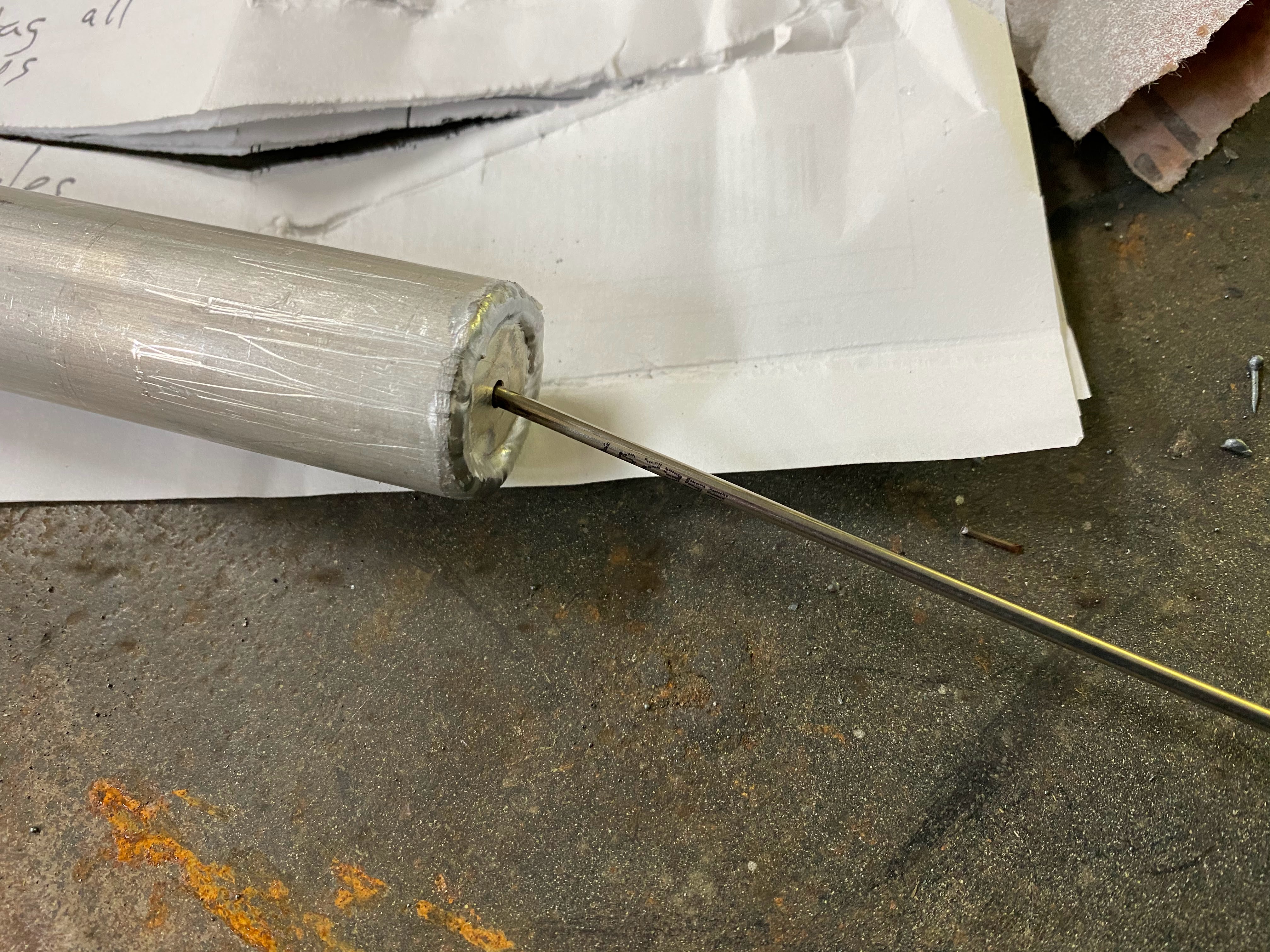
There is a .09 stainless wire that stops the tube from popping out.  On the inboard side, there is a bolt that goes through the outer tube and the wire is wrapped around it.  On the handle side, the wire is welded to a washer.

Step #1 was disassembly... I ended up unbending the wire around the bolt, with the hope of wrapping it back around after the handles have been anodized.

Step #2 is drilling the mounting holes in the fuselage.  You crawl in the fuselage with a hole saw and drill the first hole up against the forward side of bulkhead B.  Then I got out and put the tube into the first hole... using a small level I marked the top of the other side and drilled it next.

I started the holes on the inside, through the inner layer of glass.  Then I finished the hole from the outside.  The act of drilling the inner gummed up the hole saw enough that I had to get out anyway to remove the debris.

I used a 1 1/8th hole saw.  The outer tube is slightly bigger than 1 1/8.  I tested on a thin piece of wood first, and it was right on the money.


Step #3:  Getting the handles anodized.  I unwound the wire and extracted the retaining mechanism and sent the handles off.  They are nice and black.


Step #4:  Reassembly.  I put the whole thing back together and then filled the cavities in the fuselage with a mixture of resin, cabosil, and milled fibre.  Then inserted the handle from the inside, and filled the gaps between bulkhead B and the handle.


To be clear, I reassembled the anodized parts BEFORE I bonded it in place.  I just could not see an easy way to do this after the fact.  Hopefully I don't regret this decision...

Step 5:  Fiberglass reinforcement over top of the handle to bulkhead B.

Step 6: Trim the excess handle on the outside of the fuselage.  I put aluminum tape around the hole to start with to act as a buffer between the sanding disk and fuselage.  Once I got to that level, I removed it and trimmed the last little bit very carefully.  I did all this with the handle installed, so I taped up the handle and put a towel inside.  I sucked out all the shavings with a shop vac before removing.