Lots of fun ahead.
I have been putting this off, because I know it will be a lot of work. But the cowl, baffles/plenum, prop/spinner all have to work together and fit correctly.
First step is to put the brush mount on for the slipring. This is easy :-)
The cowl has to be notched for the slip ring mount, as does my cowl alignment fixture.
Next I put on the hub, blades and spinner (temporarily).
I could not resist connecting the hub to the controller. IT WORKS!
Under no load, the prop draws about 1 amp when moving. Full feather is pretty darn cool.
Installing the prop was simple.- Add slip pickup mount bracket and pickup to engine.
- Put the bushings in the hub
- Mount the hub
- Put in the hub bolts (through the back)
- Attach the blades. Blades are marked both on the hub and each blade. Align the cam, and wind in the threaded hub
- Done...
Because the shop needed to be cleaned, I pushed the plane outside yesterday. Gives you a very different view of it not in a confined space.
Next is the start cutting up the front of the cowl. Opening up the inlets.
The goal is to open them up so the inboard side of the inlet meets up with the spinner. I roughly got there yesterday.
Back on the plane, plus cut the opening for the oil cooler. It needs to be a touch larger still.
I want to get the hub and spinner put away, and also have a working surface that I can sand against. Made a ring out of 1/8" plywood, split it horizontally, hot glued it and slid between the backplate the cowl. The backplate has holes in it, and I drilled through the ply and cowl for clecos.
Next... need to sand the cowl and get it ready for bonding foam, filler, etc.
After some emails and a call with Zach, not going to go the foam route - but epoxy and micro balloons. Only slightly heavier, but much easier. New plan :-)
After HOURS of sanding... yes, hours... everything is prepped and ready for the filler. The gel coat was really thick around the prop flange. Used 80 grit paper and an air powered orbital sander - but it still took hours. I went to far as well, but thats fine as I saved the weight of the gel coat (at least that is what I tell myself).
The plywood templates have been wrapped in packing tape, and the clecos waxed just in case it runs down. Plus the crank has been bagged. Last thing is to cover the oil cooler just in case.
Used a mixture of West Epoxy, microballons, and a touch cabo. It is no where near perfect, and going to need sanding and another coat.
Every time I tried to touch something up, something else got worse - so i just left it. Once it is all dry (which will be quick with our temperatures) I will take it apart, sand it all flat, and do another coat. No big deal, just more time.It turned out pretty good.
Already have given it a light sand to knock off all the high points. The face of the flange has some gaps, so the plan is to fill those, then put the plywood back on and fill again.I thought the 2nd coat would be easier than the first, and it was not - due to some crappy prep.
On my plywood ring (that is covered in packing tape) I picked off the bits of resin that where on it. Well, I didnt get them all and its not perfectly smooth and was grabbing on the large 12" putty knife. Lesson learned - put on new tape on subsequent coats. Also, the mixture was slightly runnier than before (not enough micro). So more sanding is in my future. Not happy.
Also... The face of the prop flange needed some cleanup as well (gaps between OLD edge of the cowl and the filler), so i touched them up and then put on the plywood ring. There were a couple problems with this approach.- When i put the packing tape on the plywood, there were some wrinkles.
- I didnt put packing tape all around. The inside edge was bare wood in some places
I realized this after I did it, so I took it off before it was dry, which made a mess. After dry, I sanded it down and used a touch of body filler where needed.
All sanded now after the 2nd coat.
The top and bottom came out very nice. The sides are going to need work. I could be chasing this for days, so I am going to get it as good as I can, take it apart, and cleanup more. Once it is 95%, going to glass it (the two halves separately) and see what happens. Still need to radius the edge to somewhere between 1/8" and 1/4".
Test fit before moving onto the next step.
Looks pretty good. Need to sand down the sides by the inlets, but the top and bottom line up just as they should. The two halves are not attached at the flange, which is why its a hair off. I have a cleco that holds them in place, but cant have it installed with the hub and spinner on.Now that the spinner ring is pretty much ready for glassing, I started to rebuilt the inlets are more importantly the inboard side of the inlets where it is going to feed the plenum. Trying to get smooth airflow past the spinner inbound.
I foamed everything up with hot glue to hold it in place temporarily, then put down 2 layers of glass with peel ply on top.
The whole purpose of this step is to start the rebuild. I am going to split the center along the cowling split line when dry, and then I can start finessing it to make it look right. Just trying to get some structure I can work off. The challenge is going to be cutting the slit. I have an oscilating tool that might work, and a air saw. Hopefully one of those 2 do the trick. The issue will be access. Normally I would use a dremel with a cutoff wheel, but can't get in there to make the cut.With the peel ply removed
This should do exactly what i want / need. The big gaps are closed up and I should have a good surface to start the next step on.Next is glassing back up the expanded spinner ring.
I figured I would take a small step. In consulting with Zach, he recommended a layer of glass of the curve, and then another on the whole thing. So I started with the smallest part first.
Its amazing how the right weave on the right bias will form itself to the correct curve.
Everything not resined up is going to be cut away or sanded away.
2nd layer applied after sanding.
This time I peel ply'ed everything. After the first layer, you could really see the weave. Hopefully the peel ply works. I had to put it on it small strips because of the compound curves.
After removing the peel ply and cleaning up the edges, figured I would test fit everything again to make sure I am going in the right direction.
It all lines up pretty nicely. Needs some finessing around the cowl split behind the spinner, but everything is lining up as intended. That is a huge relief as I dont want to do this again
Just finished trimming the upper inlets after extending and re-profiling them. Started by bonding in foam and glassing against it. Sand the foam away, fill for profile (mixture of cabo and micro), sand, then 2 layers of glass on both the top and bottom, then sand again.
Now I have to do the bottoms.
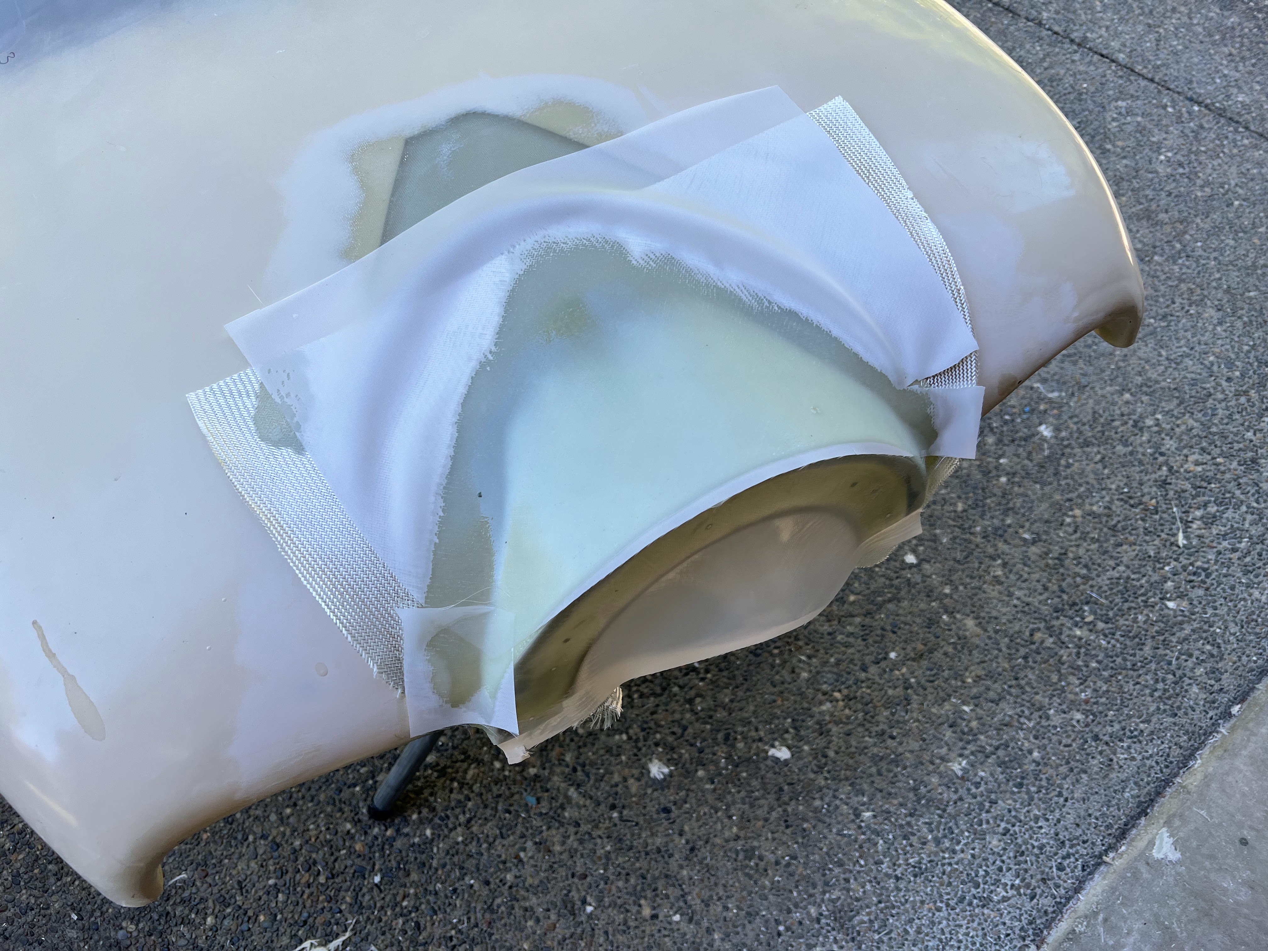
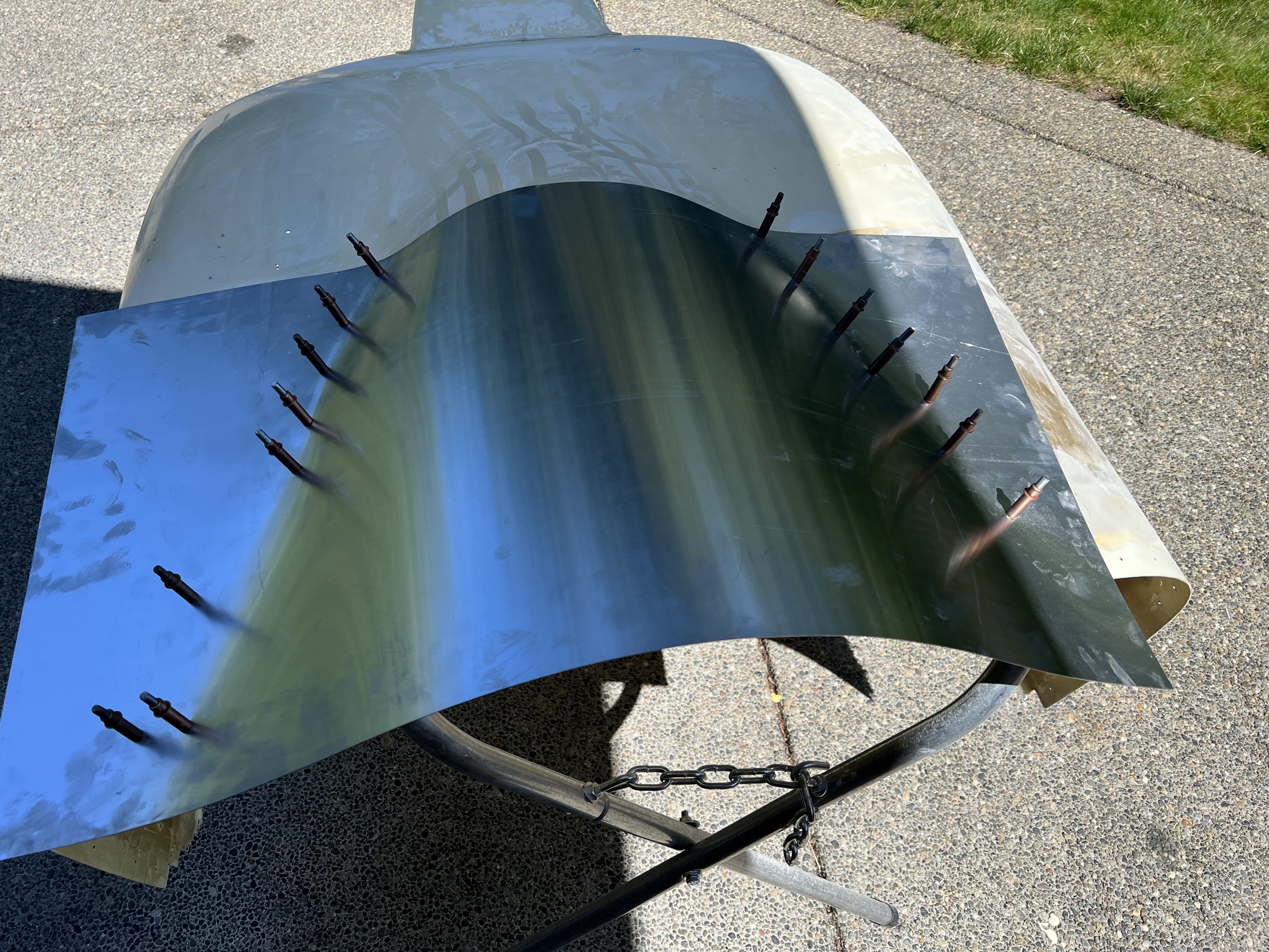
The exit air ramp at the bottom rear of the cowl needs to be extended. I've been thinking about how to do this for over 9 months. The plan is to use aluminum to conform to the existing partial ramp, and just extend it in height and width. With the extra large oil cooler and intercooler I need more exit area.
I've had the aluminum for weeks and have been staring at it.... well finally said just do it.
I started out by working one side... getting the curve right, and drilling / clecoing as I went. I think it took all of 15 min tops.
Next was trimming back and sanding the cowl. Debur a few holes, clean the mold/aluminum, mold release, re-cleco, and start mixing resin.
3 layers of cloth, 1 layer of peel ply. Once this is cured, take the peel ply and mold off... then will grove/dish the seam on the outside and put 2 layers of glass on the outside seam, then fill to flush. I will probably put a 4th layer on the entire outside. That should be plenty strong.
I want to put a lip on the aft edge of the ramp... apparently this helps draw out air. But I have not figured out how I am going to do that yet.
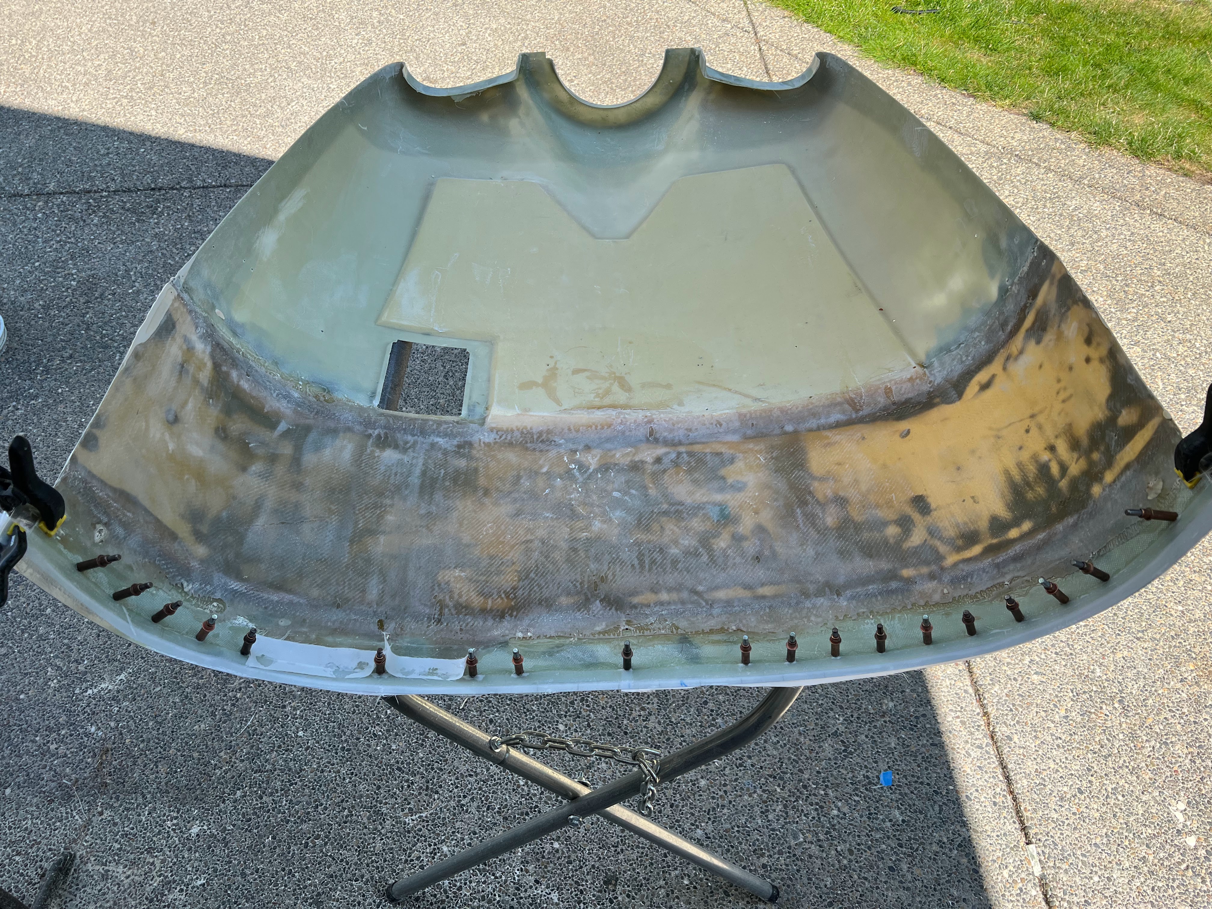
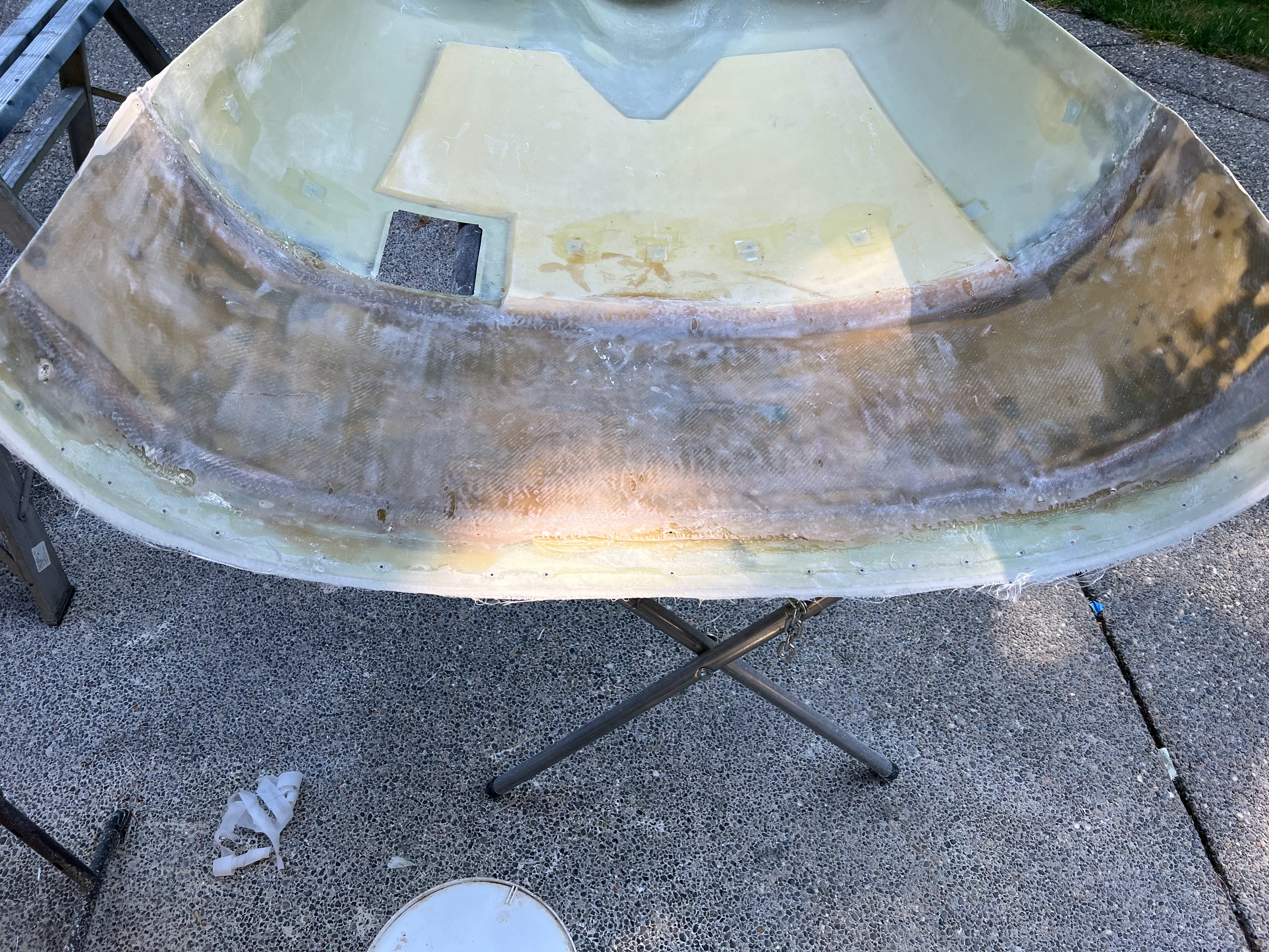
Took the mold of yesterday. It definitely worked... however it is very big. It is currently too long as well, which makes it look even bigger. The good news there is plenty of room for the exhaust.
Got a lot done on the cowl in general. Sanded the outside down in preparation for the 2 layers of glass to tie the outside of the exit air ramp extension - glass applied. Started filling the slot for the nose gear. Bonded in foam to fill the taxi light depressions, plus a layer of micro where the foam did not fill completely. 2 layers of glass on the outside of the oil cooler inlet.
Plus, I layed up 2 strips 44" long 4" wide of glass for my new cowl joggles. When I finally cut the cowl sides down the size, most of the joggles will be gone and will need to be rebuilt.
Now it all just needs to dry, and then more sanding - YAY!
If the cowl wasnt ugly enough.... after lots of sanding, working on filling the gaps from the last layers of glass.
The light depressions have a layer of glass on them. The oil cooler inlet has been faired. The outlet ramp has been faired, and I started on the last of the 'oopses' from the lower cowl extension. Tomorrow will be lots of sanding (again).The top cowl needs some love. For some reason (either erosion, or something moved or both) the top cowl does not line up with the fuselage goggle. In some places its right on, and it one spot is almost 1/8th out (erosion), and it a few places its just a hair off.
After consulting with Zach, I am going to extend the hole top edge of the cowl about 1/4", refit it, and them trim.
The mold is aluminum. For the most part, I used the holes already in the cowl to temp mount it - but added a few more where the aluminum was not laying correctly.
I taped the the top (bottom in the pic) with packing tape to try and minimize the amount of resin that bleeds through. Mold release on the aluminum, and cleaned everything. One 5/8" layer of glass with peel ply on top. Once this is cured with flip it over, give it a light sand and then another layer on top.
All gooped up.Looks like it turned out OK. I extended the edge for more than I needed. Also started filling holes...
It sure looks ugly...Test fitting after all that work... and marking the cut line
Came out not too bad... Way better than it wasSo ran into a problem. When I cleco the cowl in place, it shifts slightly to port and its hitting something hard. Finally realized its the slip ring hitting the inner ring of the cowl.
The opening in the cowl is 8" wide on the aft side (it tapers slightly with the curve of the flange). The slip ring assembly is 8 3/8". I am going to shoot for a 1/2" gap (I think that is safe), so the new inner flange will be 9 3/8".
The plan:
- Make an MDF ring the fits into the space on the inside of the cowl with room to fit the slip ring with no interference plus 1/2" or so on each side.
- Route the inside of the ring to ~1/4" radius. Sand and finish the ring, wet sand to a nice finish
- Cut out the existing flange, sand the freshly cut edge to a taper
- Attach the cowl halves
- Drill and cleco the ring in place
- 1 or 2 layers of glass on the outside. Probably 2, so I can sand one partially away
- Remove ring. 2 layers of glass on the inside
- Trim edges, cut slot between rings
- Pray it worked.
The big benefit to this change is the brush bar for the prop / slipring no longer needs a notch in the cowl. OK, minor benefit LOL.
Everything fits much better now.Finally got up the nerve to do the big cut on the lower cowl to remove the excess material (due to the stretch and reprofiling).
Now the joggle rebuilt begins...New joggle strip cut and fit. It's 3 layer of glass that was bonded up separatelyBonded in place using a mixture of resin, milled fibers, and a dash of cabosil. Clecos were spaced every 1.5". I put 2 additional layers of glass between the cowl and joggle in the extension, as it was noticeably thinner than the rest of the cowl. All the squeeze out was cleaned up after everything was in place. There was a lot of material to remove... I probably over did it a bit. I put a lot of tape on the inside to catch the squeeze out, and then cleaned it up with a bit of acetone. Once this is dry, going to add 2 more layers of glass on the inside to strengthen it up, overlapping the joggle onto the cowl.Other side done. Time to add more glass to the flange and create an overlap.2 more layers of glass on the inside to bond the joggle flange in.
Somehow the cowl has shifted slighly. I have pulled out my hold alignment jig that attaches to the crank. Originally it fit inside the inner ring on the cowl, which is no longer there. I aligned it by hand and drilled new holes for the aluminum. I have successfully got it back into alignment with the spinner.Going to work from the front to the back and align the cowl and drill the holes for fasteners.
Going with 6.4" spacing across the 39" from the aft of the cowl up to the last 5" where it curves to much for skybolt fasteners.
Also, before doing this I sealed up all the holes in the aft of the top cowl. 1 layer of glass on the bottom, filler on top.
Once everything is aligned, I put 2 new holes in the top cowl, straight through the goggle and firewall stainless. Then I used a ratchet strap to pull everything relatively tight.
Fastener pilot holes drilled on the cowl sides and top.
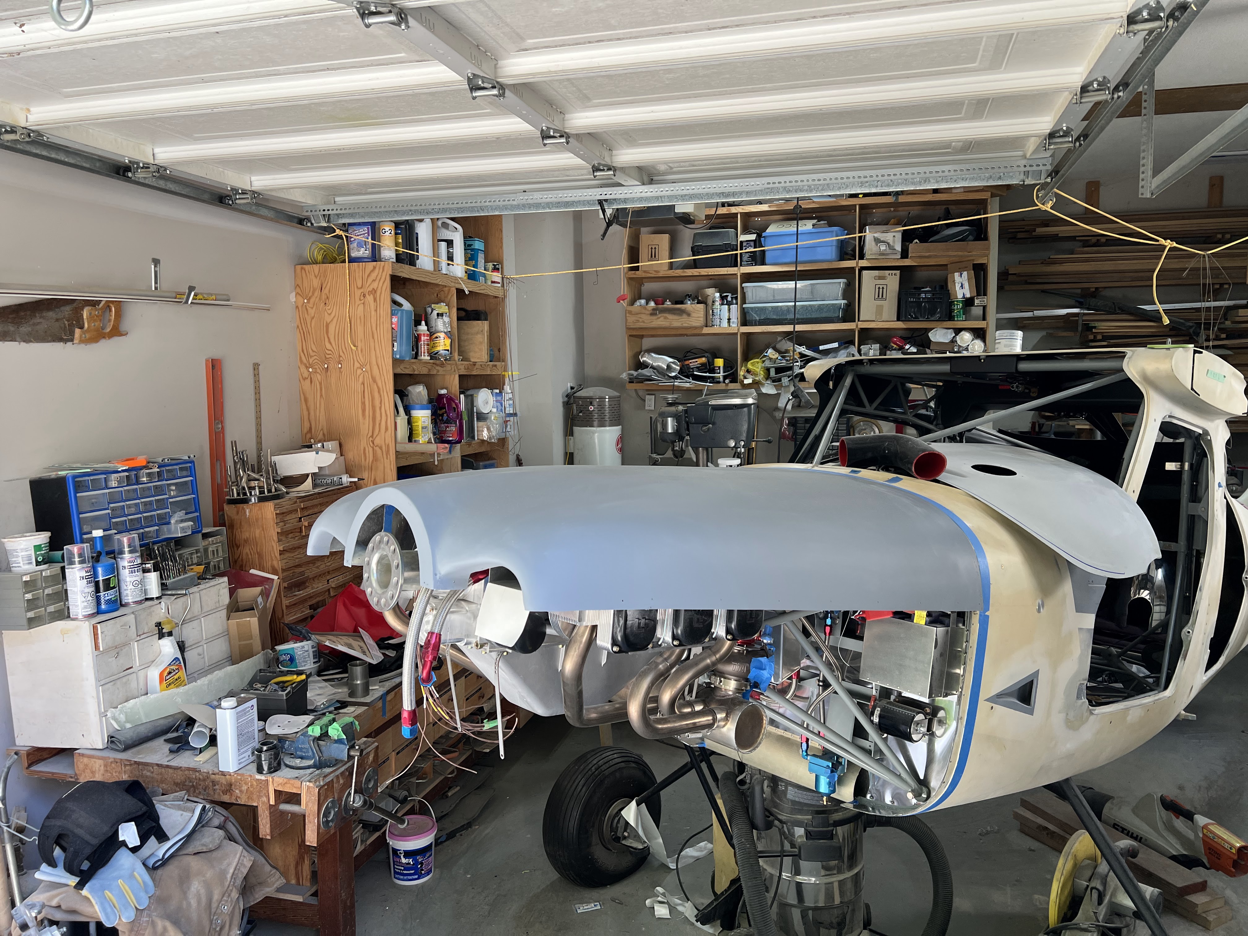
Test fit of the hub and spinner. It all lines up like it should.
Now I have to deal with the bottom, including cleaning up the exit air ramp.
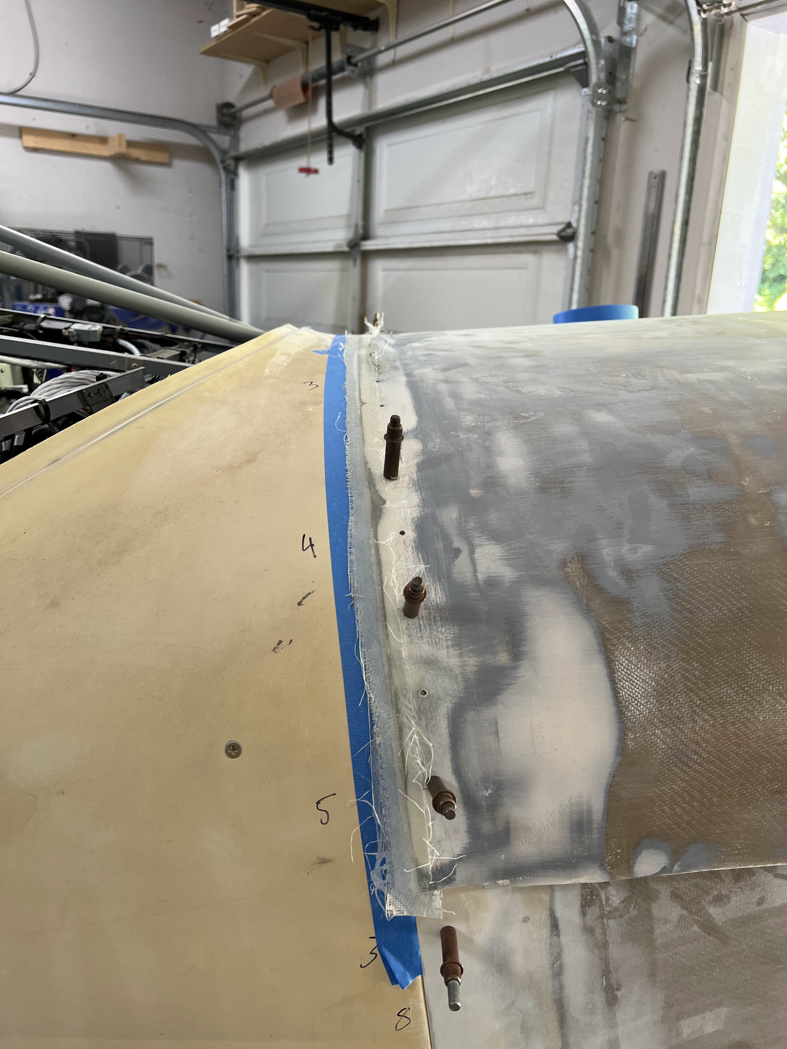
Small problem encountered with the top of the cowl at the seams for the extension. As the cowl is thicker at that location, it wants to bend less - so is not sitting nicely in the joggle. You can push it in with your finger. The plan will be to relocate the fasters to these 2 areas on each side to get it to suck in. That will mean respacing all the fasteners - but its worth it if it works.
Working on the top/bottom cowling seem at the front.
Same picture as above, but after lots of sanding and filling. All of the 'real' faster locations have been drilled and the cowl is now rock solid. Because the cowl has been on and off so many times many of the holes had started to oblong and the fit was getting sloppy. Its all good now.
So it's time to prime. I could keep chasing defects, but my current theory is a high build primer will eliminate the small stuff, and then I can focus on the big stuff.
Initial impressions are really good. I am using a SEM rapid primer / filler procured from the local auto supply shop (Lordco).
Most of the minor imperfections are gone - which is great news.Before sanding
There is a fair bit of stuff that needs addressing, mainly around the ends (cowl trailing edge, and the inlets where they have been enlarged).After initial sanding.
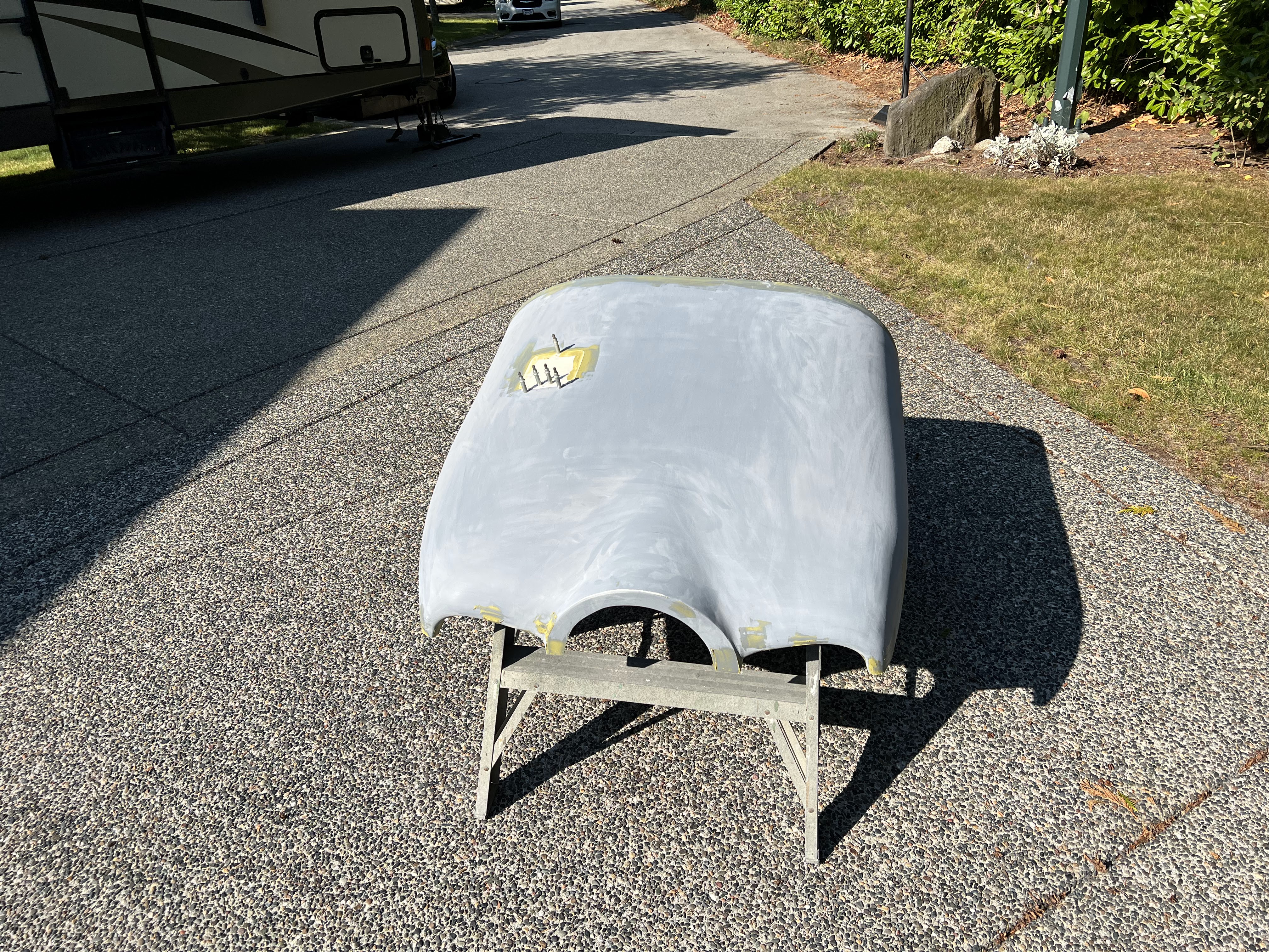
I did the cowls in separate stages. Started with the top because it was 'better' (less defects), and I had not final sanded the bottom cowl yet. After sanding, I went after all the little issues.As for filling... up until the primer stage I used West Systems Epoxy with their 410 Microlite Fairing Filler. I can mix this up in larger quantities, and depending on where I am filling I can add Cabosil, Milled Fiber and/or Filler and I can adjust the quantities to get the necessary consistency / strength. Now that I am at the priming stage and going after the little stuff, I am switching to Total Boat / Total Fair fairing compound. Total Boat works really well for the fine details.The upper cowl has been primed, sanded and filled and is drying - so onto the lower cowl. Unfortunately the lower cowl has been butchered, extended, reworked, stuff added etc. It needs some love. I am very confident in its strength... now I have to make it look beautiful.Prior to priming...
I am using my 'shed' for the RV. Its covered and somewhat sheltered from the wind. Prior to doing anything, I water down the area where I will be working with water to keep the dust down. I usually start on the top surfaces, and then flip it over and work on the bottom.Doesn't look to bad in the picture, but in reality it looks like an obese person wearing yoga pants (that shouldn't). Lots of defects. But man, it sure is nice to see everything one consistent colour and not a hodge-podge of crap. Plus, the SEM Rapid Primer Filler dries really fast, which is awesome.Test fit after 2nd run of primer / filler.
It actually looks not too bad. There are a lot of little things to chase. The seams between the bottom and top halves need work, and there are some little pinholes. But, basically its together. Everything lines up.
Here is the progression over a year....
I stopped working on the cowl in approximately October 2022 when the weather cooled, and started up again in June 2023.
So today has been all about chasing gaps between the upper and lower cowl. They were not consistent. When I marked the cut line, I used a long straight edge and clamped it to the cowl. However, the cowl curves, so the cut line had a curve on the forward end. Its not huge, but you have to follow it. I made the decision to do small portions of the gap individually... which means lots of top cowl on and off. More work and longer, but it seems to be paying off. Working to get to a consistent ~1/16th gap from the back to the front. Sure would have been easier to just hold my nose and buy a Lycoming... especially with all of the UL issues of late.
Started installing fasteners along the upper cowl aft edge. Its coming along...
Going to leave the rest of the cowl for now and focus on windows, oil cooler, intercooler, etc. The cowl is 90%+ complete thankfully.