Search This Blog

Showing posts with label UL520T. Show all posts

Wednesday, 24 June 2026

Boots and cooling

Been having both cylinder and oil cooling issues.

The middle cylinders (3 and 4) were warm and getting into the yellow regularly on climb out.  I added some fins attached to the underside of the plenum top to push air down into the middle cylinders.  Worked extremely well.  Google Gemini helped me with this and was spot on.


The deflector is 2.5" wide, 2" long and bent on a 2" radius.

Gemini did such a great job, figured I would see what it would recommend for my oil cooling.  Gemini recommended building a diffuser.  So I spend a day and built what I felt it recommended.

The basic principle is the keep the air moving at high velocity and not just have it spill out into the lower pressure area inside the cowl.


Did not work.  Oil temps were hotter.  Luckily I attached it with screws, so taking it out what not a huge job.

But during the process, I discovered that the January 2026 version of the operations manual has increased the upper green limit for oil cooling from 212 F to 230 F (from 100 C to 110 C).  If this is the case, then I really dont have an oil cooling problem, but I would still like to get it better.

The plan for this week was to head to the Glasair Flyin at Smiley Creek Idaho.  The weather does not look good.  But, I wanted to get the rubber boots on the horizontal stab before going.


The local AMO where I sourced the boots educated me how they adhere them, so I followed that to the letter.  It did pain me to scuff sand my paint job, but it had to be done.

Last step is to edge seal the boot using PRC.  That is today's job.

Saturday, 15 February 2025

2nd Engine Start, Debugging and First Taxi

Another good day today.  Video here.

First off fixing things... 

  • Brake fluid leak at the park brake.  Tightened, and added additional fluid.  Tested brakes, all good.
  • Fuel leak at the banjo fittings on the collector to the pre-filters (before fuel pump).  The leak had soaked the fire sleeve on the hose.  Replaced the fire sleeve, rebanded the fire sleeve, and reinstalled.
  • Checked the EGT/CHT connector on the EMS.  Tight.  Checked the EFIS, and all 6 EGT's and CHT's appeared to be reading OK.  More on this later...
Purged the system of air by running the pump for a bit.  I didn't get it all out, as it was a bit cranky to start.  Ran fine.

Once warm, went up to 1800 RPM to do a 'mag' check... just check each ignition system.  Right ignition system running rough and backfiring.  Left it on the left side (ignition 1).

Same issue as before.  4 EGT's and 2 CHT's not working.

Went up to 2000 RPM on a single ignition.  Ran smooth.  9.6 GPH, 40.3" manifold pressure.  CHT's in mid to low 200's, EGT's mid 1300's.

After letting the turbo cool, we put the cowling on.  I want to check for any interference issues with it running... anything to fix now before paint.  Cowl went on super easy.

2nd run was cowled.  After warm up, went to 2000 RPM, and then briefly up to 2200 RPM.  Arms started waving to shut down... the wing nut clecos were departing the windshield.  
2200 RPM
  • 40.3" manifold pressure
  • Fuel flow 12 GPH
  • Manifold inlet temperature - peaked at 29.8 C
  • EGT's - mid 1400's
  • CHT's - low 200's
Checked both COM's.  No static at all on TX or RX.

Did a quick taxi, because I could :-)

Post run diagnostics.
  • Ignition issue was 2 plugs swapped (4 and 6).
  • CHT / EGT issue tracked down to polarity.  I remember when installing them and thinking about does polarity matter?  At the time I thought not... now I know.  Fixed and tested with a heat gun.
  • No leaks
  • No rubbing
  • No burning
  • Turbo exhaust pipe has a shake.  Needs an additional mount.
Other than that, a success.

Tuesday, 11 February 2025

Post First Engine Start - Review

The day after the first engine start I took a detailed look at everything firewall forward to see what I could see.  Overall, results were positive.

  • Slight fuel leak on the banjo fittings going into the pre filters (before the fuel pumps).  This leak has soaked the firesleeve on the line between the inlet and the firewall.  Will replace that firesleeve.
  • Everything prop related looks good.  Nothing untoward on the slip ring.
  • No chaffing on any wires
  • 3D printed inlets attached to the plenum show no signs of heat distortion.
  • Exhaust looks good
  • The engine puked its preservative.  This primarily came out of the slip joints on the exhaust and appears easily cleanable.
  • Oil level is good, and no discolouration at all.
  • Oil cooler appears good
  • Overall, everything survived AOK.
  • Downloaded the logs from the EFIS and loaded into Savvy.  EGT's 2, 3, 5 and 6 show 0.  Need to check configuration and/or wiring connections.  CHT's 3 and 5 also show 0.  Same check.
    • Note:  Advanced has added functionality that every engine parameter can be picked up off the CANBUS or discrete sensors.  Everything in my configuration is coming off the CANBUS EXCEPT the EGT's and CHT's.  I may have not flipped the ones showing 0 to discrete sensors through the EMS.
  • Talked to Tracy who has the same engine / prop and is flying.  He noted my MP is higher than his.  I had some of his logs and checked, and yes - about 2" higher.  But it was far colder (density altitude -980 feet the day the engine was fired) and very close to sea level.  This is something to watch.
  • Fuel flow at idle 1.6 GPH.  Fuel flow at 1500 RPM 4.1 GPH.
  • Weeping at the fuel drains on the main tanks.  Not surprised as I did not seal them as they are coming out for paint.
  • The header tank has 2 ultrasonic sensors to show fuel level.  The 1/3rd sensor warning goes off when the pumps are running.  Guessing this is due to turbulence at the tank due to suction from the pumps.  The 2/3rds is rock solid.  Tested this with the engine not running and behavior is the same as when the engine is running.
  • Fuel pressure consistent in the mid 30's.
  • I have two current sensors.  One shunt that shows everything to / from the batteries, and one on the engine bus (hall effect sensor).  At idle, the engine bus (ECU, coils, pumps, etc) was pulling 9 amps.  At 1500 RPM, 11 amps.
Overall, the only thing that needs to be 'fixed' is the leak, and the problematic EGT's and CHT's.

Saturday, 8 February 2025

First Engine Start!

The day finally arrived!

Was not sure it would happen today... we had snow this week, and needed to clear the snow to be able to get the plane out.  Huge thanks to Geoff for clearing most of it with his ATV and plow.  SO GRATEFUL.

We had tested the fuel system to the firewall, but not the engine side.  So that had to happen first... Had a few leaks, but one that was a bear.  Something was leaking at the gascolator.  When I made the mount, I copied the Glasair design.  Usually the gascolator bring fuel from the firewall, but in my case that is NOT the case, to the bracket that holds it is offset from the firewall, and there is a 90 degree NPT to Flare fitting on the rear of the gascolator.  That is what was leaking... The fitting was not tight, and was not sealed.  That meant that the gascolator had to come off.  Long story, but that is now fixed.

Fixing that fitting meant taking off the fuel lines, which meant air was introduced into the injection rails... which meant it did not want to stay running until we got all that out.  Eventually it happened.  Oil pressure came up no problem.  Manifold Air temp was showing about 10 degrees above ambient.

I have very little (ok, NO) turbo experience.  Idle speed was 910 RPM, at just over 30" of MP.  At 1500 RPM, 34".  That just looks weird.

Charging system is working.

Prop is working.

CANBUS is working.

Pretty exciting day all around.  So damn grateful for all the help.

Video HERE.


Monday, 12 August 2024

Airbox / Air Intake


Moving closer to the end...  Need an air intake for the turbo.

Lots of ways to do this.  My preferred method is to mount the box to the starboard side of the cowl and have it captive.  IE the filter and box and 'scoop' are all one.

UL has a part... which I was initially unimpressed with.

I bought a part from the US distributor, which initially I liked... but its very tight and restrictive.

So I am blending the two, and hoping for the best.

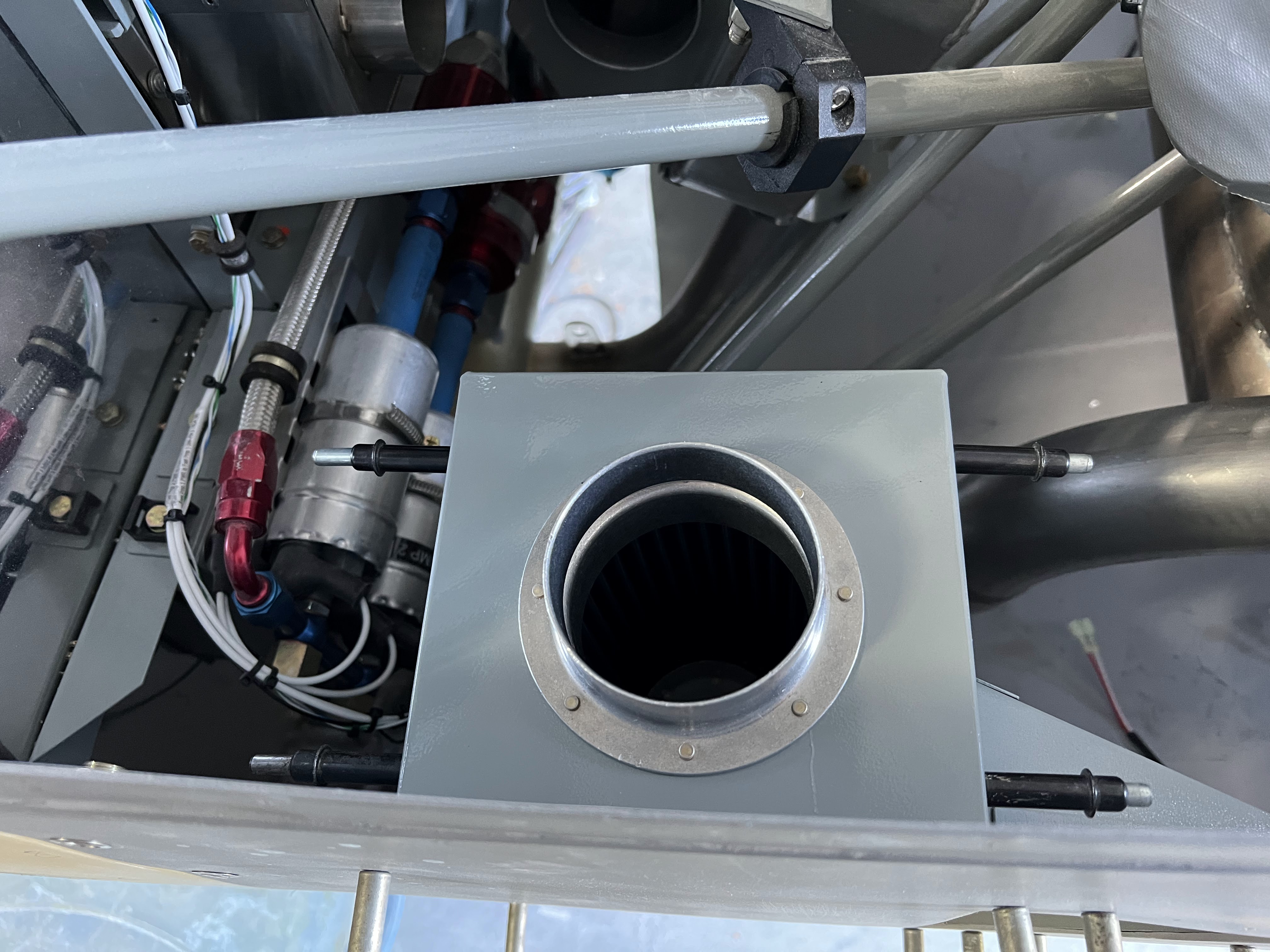
The box is the height of the filter that came with the engine, and I make it 6" square.


Drilled and clecoed.  The plan will be to have the top removable for filter cleaning / replacement


Pretty basic design.  I needed to tweak it a little bit, but now I need to mount it.


This is kinda sorta how UL does it... but I need to integrate in a alternate air source that bypasses the filter.

Now I have to build the scoop...  It is just going to be aluminum as well and NACA-ish, but not a NACA.


Next.... alternate air inlet...

The first challenge was to work out the angles... and not interfere with anything, and keep it away from the exhaust as much as possible.

I used a flange to get the size, and started with a paper tempate.  

The 'door' is a 2 piece assembly.  I want it to slide as nice as possible, so I used some high density plastic on the top that will contact the flange.  The two pieces will be flush riveted together, and the flange on the box will be flush riveted as well.

Mock up below.


I bought a 2" linear actuator from Actuonix.  Slick little unit.  They also sell a lit push button, which looks really nice (standard switch used in custom hot rods, etc).  BUT THE WIRING DIAGRAM IS WRONG.  And all the colours on the wires are wrong.  That was frustrating.


I am going to draw this up and it will be part of the electrical diagrams.

The best part is IT WORKS PERFECTLY.


All parts have be deburred, alodyned, and primed.  One fell when I was hangiing it and bent... and got crap all over it.  Will need to be sanded and redone.  All the rest turned out good.

I found some waterproof limit switches on Amazon.ca.  Super simple and inexpensive.  I mocked it up with the existing wiring to the LED indicator on the panel, and it worked as expected.  But I didnt do enough homework... the screws are really small.  Ordered these on amazon... I now have a lifetime supply of 2mm socket cap screws :-).


This is done, except for riveting it to the cowl.


Monday, 27 May 2024

UL Regulator Cooling

Ul recommends that the regulator be cooled with some fresh air.  Apparently in the past there have been issues with hot regulators.  The one UL520T that is flying does not have any blast tube, and has been fine for years.  But, might as well do it as I have the space and its easier to do it now.


Simple C shaped bracket that picks up the regulator mounting holes.  The large holes on the front sides are for screwdriver access.


Bit of a pain to line up and mount, but doable.  Just needs finishing and its done.  Will do with the next batch of parts.


Tuesday, 21 May 2024

Exhaust

 The UL engines comes with exhaust, muffler, etc.  Its all stainless, and very nicely welded.

There are two pipes... one off the turbo, and one off the wastegate.  Both are on V bands.

The OD of the pipe coming off the waste gate is ~2.38" (60 mm) and the turbo is 2.75" (70 mm).

The rough plan is to come off the pipes at a 45 heading towards the center.  Then another 45 to head out the bottom.

Note:  The waste gate can be rotate.  Mine was hitting the outlet pipe until I rotated that.  Once I rotated the waste gate now I can have the exhaust pointing straight down.

Going to mock everything up in place, tack everything, and then take it apart and get it finish welded - at least that was plan A.

Talked to the US UL Distributor, and asked what is the size of the pipes.  The response is "METRIC".  So where on earth can you find metric exhaust parts in North America?  I have found some, but they are not plentiful.

Ray (UL US Distributor) thinks that the factory can make exhaust with the correct tubing.  That would be good, but then the question is cost and shipping cost.  Regardless, I still have to mock everything up.

I bought a bunch of bends and fittings from the Aviation department of Amazon.  Here is what I discovered.

  • 2.75" tubing matches up really well with the 70mm exhaust.
  • 2.5" tubing slips over the 60mm wastegate end.


I have not cut anything yet.  Just wanted to get an idea where to go next.  I think this is going to work.

After staring (and cursing) this for weeks, I am giving up.  Going to find a shop that can just weld this up and I pay the bill.  Stupid god damn metric pipe.  I cannot find a good source for metric 316 stainless.

Contacted Hilder Rosales today at Hard Industries in Arlington.  Going to Arlington Skyfest next week, and will take him the stubs and see what he can do. I have had enough for searching for parts... I WANT AN EASY BUTTON.

Also, I contacted and heard back from UL Power.  They can source me 60mm and 70mm pipe and bends - just need to know how long.  Shipping is going to be expensive...  There is a new distributor in Canada and he is going to bring them over with his next shipment.

So fast forward 5 weeks (now early october), and I still dont have my exhaust bends.  The new Canadian distributor says that DHL is not reporting location, and they should arrive any day now.

Fast forward to January 2024.  Still no progress.

I was lamenting to some friends that I have no experience here.  So we had a building day... and I now have a TIG in the shop (on loan).

This should not be very hard... it really shouldnt.

So as I step 1... we put the lower cowl on, and mapped out using a piece of welding rod where the exit is.


Next... I need to fix the tips in place off the bottom of the fuselage and start working my way forward to the engine. 

February 2024.  PROGRESS

So I made a bracket using the air deflector fasteners as the holding point.  Then I bought some hole saws that match the tip diameter.  Voila..


So after cutting and grinding and fitting, I have one pipe.


It is not tacked yet.  I used tongue depressors and hose clamps at the joints (thanks to Bob for that trick).  Need to start on the 2nd one after I get home from the next business trip.

2nd pipe in place and close...


So after a bunch of fits and starts (long story...), I have exhaust.


Next is to build the mounts... and send the pipes for ceramic coating...


Monday, 20 May 2024

Oil Cooler

The UL power engine needs lots of oil cooling.  The US distributor does not recommend the UL cooler, and nudges people towards a standard aero classics 13 row cooler.  So that is what I bought.

To get lots of oil cooling, it is recommended to put the cooler under the prop attached to the engine.  UL makes brackets to this location, so I bought it from their US distributor (Wicks).  For the price it wasnt worth building.

There is also an oil cooler adapter that mounts up front under the oil filter.


The bracket is quite large.  Not sure if I will use this or make a new one.  Proceeding with mock up anyway to learn what i dont know (yet).

Used a pieced of 1.25 x 1.25 aluminum angle to bridge the gap and to tie in the shock mounts.  Needed to shorten the port side 'leg' that attaches to the front of the engine.

With the bracket all the way 'up', and on the angle that the bracket specifies, the cooler is still touching the cowl, but much less than it was when I started.

Used a double exposure method that I have really wanted to try since I heard about it.

Cooler mounted to engine, no cowl


With cowl and 1" tape grid around roughly the correct area.


Overlaid the two pictures in MS Powerpoint, and made them both 60% transparent.


This should get me very close on initial cuts.  Finessing will be required.

Tip(s):
- I bought the 'silent block' mounts as recommended by UL, as well as the M8 lock nuts.  They really are lock nuts... so during mock up I went down to home depot and bought M8 non lock nuts.  Much better for mockup.

After staring at this for several months, I am going to build a new engine bracket.  The UL bracket is way to big and unnecessarily heavy for my cooler.  I have a large chunk of aluminum angle that will do nicely.


Need to build the struts next.  I have the UL struts, and am just planning on using them as is.

Because I built the new bracket out of thicker aluminum, I doubt I will be able to bend it to get the ~12 degree angle that the UL bracket has.  I did flip the bracket on the cooler around to push it farther back.  But it appears to have less room than it did before.


Need to cut out the cowl pretty soon and make the inlet.

Inlet cut.  Its on a slight angle, but I am OK with that.  I dont think it needs to be straight up and down.


I had been pondering the mounts for months (well, it seemed like months).  I recently ordered all the fittings and figured it is time to go for it.

Fitting notes:
  • All of the hose fittings on the cooler adapter are -10AN
  • The fittings on the aero classics oil cooler are 3/8" NPT (not 1/2" NPT as I was told)
  • 3/8" NPT to -10an is readily available in multiple configurations
My goal / hope is to keep the fittings at the top of the cooler.  This will make the lines shorter and lighter.  Flipping the cooler upside down meant trimming the bracket holds the assembly to the front of the engine.  As a starting point, I decided to use the UL rear brackets.  I am not sure if they are going to work, or even if I want them to work.  They are simply about 1/8" think stainless with holes it in, and you bend it to your configuration.  Gotta start somewhere.


Made a bracket at the bottom to capture the 3 holes on the bottom cooler bracket.

The fittings all look good for a first pass, except the pilot side fitting is going to change from an elbow to a straight fitting.  Also probably changing the oil cooler adapter fitting from a 90 degree elbow, to a 180.  Will try it and see if it fits.

Now that the cooler is fixed in place I need to do the fiberglass work for the inlet on the cowl.  My original plan was to make the mold out of MDF.  However, after rebuilding the inlets using foam I am starting to see the benefits.  Super fast and easy to work, and you can just sand it away when you are done.  So I think that is the method I am going to use.  Where it is captured between two pieces of fiberglass, I may just leave it.  Its definitely light.  Also going to build it in place.  Hopefully this is not a bad idea.

Quick test.  Put a piece of packing tape on the cowl... and then stuck a piece of foam to the tape with hot glue.  Seemed to hold well enough.  So that is the plan.  Tape up the sides, cut foam to fit and build the mold on the cowl installed on the airplane and see what happens.  Going to tape up the oil cooler so nothing gets on it.

Well version 1 completely sucks.  Need to start somewhere, but this needs significant work.


The below is a cowl off a Rans S19.  I need to make it look something like this.


Built the foam up significantly (x3).  Now its shaping / sculpting time.  I dont think this is my forte...

So I took a stab at it.  The foam is super easy to shape.  But, I am realizing I didnt build it up enough forward.  Going to extend it an inch.  I need to fix the inboard section first, sand it flat, and then more foam.


It needs to flow into the rest of the cowl.  I have a feeling I will be at this for quite a while.  I want it to look 'organic' (can't think of a better term currently).


Built it up more and started shaping again...


This is starting to go in the right direction.  Nowhere near done, but starting to not look like a minecraft character.

I spent a couple hours fine tuning the shape, and it doesnt look bad (for what it is).  Unfortunately its big, and I need lots of air through it.  I figure I am going to have to redo it completely, so I might as well learn everything there is to learn, so go ahead and glass it.  If it doesn't work out, I have learned something.


I am planning on 2 layers of glass, but I have really bad luck trying to do multiple layers at once and I will do the 2nd layer after.  I applied peel ply to much of it in small pieces.  No way I can cover it in one piece with all the curves.


Packing tape was applied almost everywhere (not the bottom corners).  So hopefully this will pop off easily.  If not, I will have to remove the foam - but will see.  It is not going to be perfect - lots of filling and sanding will be required - but gotta start somewhere and learn.  This is completely new to me.

Success!  After applying a 2nd layer of glass and letting it cure overnight, I started the process of removing it from the cowl - but first I drilled 6 holes for registration (2 on each side and 2 on the bottom).  The packing tape worked... so after some gentle pulling in multiple directions it all popped off.  Then I dug all the foam out using different size chisels.  Because the foam was multiple layers, it broke apart fairly easily.

I rough trimmed off all the excess fabric.


Next is to trim down all the flanges and clean it up a bit, then I need to open up the hole in the cowl to the inside edge of the inlet.  The plan will be to bond it on after trimming and sanding the cowl using cabo and resin, then a layer of glass from the inside of the cowl to the inside of the inlet. Then a layer on the flange, then fairing compound to make it all blend in.

I started cutting the cowl, and THOUGHT I left myself an easy quarter inch to spare so I could inch in on the inlet.  Well, its pretty much right on for the sides, but the bottom needs to come back a fair bit more.

What it looks like on the plane...


Its not horrible, but I am not in love with it.  It should be very functional, which is the most important.

I temporarily installed the oil cooler to fit the inlet.  I figured now is the time to do this as the inlet is removable.


I trimmed a bit too much on the starboard side.  Plus the bottom needs some fixing.

Its starting to look not too shabby.  Its growing on me I think.  Either that, or I dont want to start over!


I've opened up the hole in the cowl significantly to line up with the outer edge of the inlet.    Its not all the way there yet... will do the final trimming once the inlet is bonded in place so I can glass the inlet from the back and the front.


I also added 2 layers of glass on the bottom forward lip and the inboard sides.  I over trimmed in some areas, so had to build it back up.  Still more to do, but its closer.  Its easier to do all this now with the inlet removable so I don't have to constantly take the cowl on and off.  The part is significantly stronger now, and I have extra material so I can clean up some off my gaffs.

Now its time to bond it on.  The plan:
  • Initial bond with resin / cabo.  Smooth the edges as best as possible, let cure.
  • Fill the edge between the inlet and cowl with resin / cabo again, and taper it
  • 2 layers of glass on the inside and outside
  • Putty wipe the outside
  • Sand
First step was to sand off the gel coat / primer around the outside.


Fit the inlet, and sand down the inside to meet the inlet.


Resin / cabo, and clecod it in place.


Test fit


So many months later... I have never been happy with the UL aft cooler mounts.  

After talking with a buddy, he offered a solution of a triangular aluminum mount.  So off I went...


Way more stable, and actually lighter.

The CAD model (Cardboard Aided Design) was perfect first time amazingly.

Cowl fits really well - thankfully.

The aft of the bracket is wobbly, and needs a bracket to tie the two of them together.  That should be easy.

Now its all about finishing on these brackets, and reinstalling.

Done.  All finished and installed...  Just need to pressure test the oil lines, put on the fire sleeve.