Search This Blog

Tuesday, 24 August 2021

Gear leg fairings

The build manual gives to options for gear leg fairings.  Aluminum or Fibreglass.

For aluminum, the fairing is two pieces (an upper and lower due to the flex in the spring gear), and  wrapped over the leg, with a foam support structure to keep its shape, with a piano hinge on the aft side to hold it together.  The brake line runs down the aft side of the leg, and holes are drilled in the foam for it to run through.

For fiberglass, the brake line is bonded to the aft side of the leg, and then foam is glued over top and shaped into an airfoil shape (using the front side of the leg as the leading edge).  Fiberglass is layed up on top of the leg / foam, and then finished.

The kit comes with material for both options.

The below describes my 2nd attempt.  The first didn't work out quite right.  Close, but not close enough.

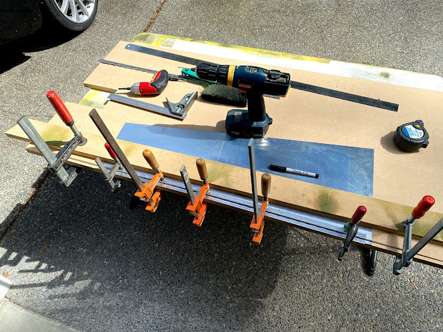
The trick here seems to be that you need the piano hinge to line up exactly the same on both sides.  I accomplished this by laying both pieces of aluminum on the edge of a bench (leftover from my wing jigs).  Clamped it down, and then laid the piano hinge down and drilled it in one piece over both sides - with the intent to cut it later.


I predrilled all the holes on the piano hinge, then clamped it down to the table as well.


Once I had drilled everything I could, I drilled some extra deep holes into the wood and clecoed to the bench.  Then I could remove the clamps and drill the last couple holes


To put the bend in the skin, the manual recommends wrapping it around a broomstick.  On my first attempt, I wrapped it around an axle, and it worked OK.  However, the RV guys use a trick to bend their ailerons and flaps.... Make a channel slightly wider than your bending form (AKA broomstick), and then lay your material down, and force the broomstick into the channel.


I raised my tabletop up off the bench to get clearance.  I had some scrap MDF strips laying around (about 3" wide) and clamped them to the top.  Again, needs to be a hair wider than your broomstick.  Mark the centrelines on your piece, line it up, and push the broomstick down.


I used clamps to force the broomstick down.  In the past I had glued / screwed this contraption together, and then you can just straddle the piece and step on the broomstick.  Clamps work once you get them aligned.

This also worked out nice for taping the trailing edge.  Leave the piece in the form, apply tape (I used Gorilla brand duct tape) to one side, then aligned and pinch the trailing edges together and push the tape over the top.  Worked out real nice.


And voila!  Bent and taped...


The above is both pieces (upper and lower).  I fed the lower down through the top to check the overlap.  I need to take about 3/32 off the lower piece before drilling the other half of the piano hinge.


You can see my first attempt the lower part of the gear leg.  Also, you can see the mounts I have made...

After trimming the lower leg to fit inside the upper, I marked and drilled the 2nd half of the piano hinge using the same method - but with the 2nd half of the piano hinge clecoed in place.


At this point, the piano hinge is still one piece.  I figure this is the best way to make sure it lines up.  Need a small gap between the two halves so there is room for it to wrap around.


Two halves joined with the piano hinge.  The alignment is pretty good.  The lower half needs a small trim on the trailing edge for them to line up perfectly.  The nice thing is its super easy to see now.  Will take it to the sheer in a couple days.


Overlap detail.  No real way around this.

Left hand gear leg fairing installed.


I am fairly happy with this one.

Now I just have to replicate it one more time...


Sunday, 15 August 2021

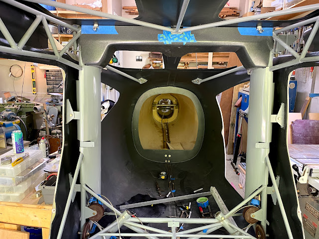
Crossover Cable Cover / Vertical Pillar Covers / 4 Point Harness Bar

 Back in January 2021 I purchased the upper cable cover from Glasair.  Well, finally getting around to installing it.

On newer Sportsman cages, there are 4 tabs along the front that it mounts to.  I don't have those.

My plan is to pickup to outer fuselage mounts on the front, then make a bracket that can be hose clamped to the cage tube in the middle.  The rear will be 4 composite L brackets bonded to the fuselage shell.  This is how Glasair does it (well, the rear at least).

So far the cover has required a bit of tweaking.  The cutouts for the tabs shown in the picture were not present, and the outer contour did not match my cage tubes.  But was still a lot better than building the whole thing!  Also, I don't think the cover will fit with the vertical cable covers.... but will find out shortly.


The crossover cable cover definitely interferes with the vertical covers.  So I marked it out using templates, and cut it back using a dremel and drum sander.  The starboard side cover was interfering with the diagonal tube off the horizontal bar under the seat, so it was dealt with as well.

Then there is the seat belt harness bar.  There appears to be no provisions for the harness bar clamps in the vertical pillar cover.  So these corners were 'relieved' to make it all fit.


All the cuts need to be cleaned up, and I am going to wrap the vertical pillar covers.  Depending on the extent of refinishing for the crossover cover I will either leave it or repaint the same as everything else.  Undecided at this point.

My main point of 'pissed-off-ness'.  The vertical covers were finished.  The crossover cable was finished.  The harness bar was designed and published AFTER both the vertical and crossover covers were purchased.  WHY THE HELL DO THEY NOT FIT.

My cage had the 3 point bracket on the vertical pillar, and the cover did not have a clearance for that.  Well, I get it.  Due to its age, that makes sense.  But it doesn't have the provision for the harness bar either.  So what gives?  One of the two options should have a provision to mount it.  This is EXACTLY why I get so frustrated with Glasair.  Someone just IS NOT THINKING.

Rant off.


First composite L bracket bonded for the crossover cable cover.

To make the L bracket, took 2 pieces of 3" wide MDF and screwed them together.  Then applied liberal amounts of packing tape.  6 layers of cloth, with peel ply on top.  Cure overnight, pop out of mold, run through table saw to straighten the edge and then chop into 1.25" sections.

Covered the area with aluminum tape, leaving the area to be sanded exposed.  Sand, vacuum, etc.  Mixed up a batch of thick resin / cabosil / milled fibres.  Was thick enough to hold itself in place while bonding.

3 more to go!  Should be easy now that I have a process...


All in.  Just needs to dry.

My brother in law gave me a big roll of aluminum tape, and I used it to mask off the sections for sanding and bonding.  Once bonded, just pull it off.  Seems to work well.


Pilot holes drilled through the crossover cable cover and aft tabs.  Now onto fasteners.  Using #8 captive fasters and not self tapping screws.