I ordered the intercooler from UL Power USA in the summer of 2022 when I ordered the prop. Due to supply chain issues, price increases, change of vendors the brass tacks are finally hitting in late January / February of 2023.
The question was... orientation of the inlets and outlets. The other Sportsman that is flying has his intercooler up high in the engine bay, aft of the engine, just under the engine mount. He has air temp issues, and is trying to get more air to the plenum.
My tentative plan...
- Enlarge the front openings in the cowl slightly
- Use ~1/3rd of the opening to feed a 3" scat tube on each side. Run that scat pipe in parallel with the cylinder heads and feed a plenum attached to the intercooler.
- The big reason for doing this is it will all be fixed to the engine / baffles. There will not be any hoses (well, other hoses) attached to the cowl, so the top will just come right off. At least that is the theory / plan.
The plan has one potential flaw. The plenum will be on the back side of the intercooler and push the air forward, and it will hit the ring gear. The alternative is to push it back into the pumps, filters, and coils. That is a bad idea...
Putting it on any angle just spreads the heat. I think having it hit the ring gear (and mix with all the air coming down from the cylinder head baffles and go out the bottom) is the best compromise.
Below is the drawing I received from UL...

I mocked up the basic dimensions in cardboard so I could play with it. So it was arts and crafts day... the dixie cups are the inlets / outlets. I really wish the engine was on so I could play with it a bit more...
Note: I had not planned on doing this, so I hurriedly clecoed in the firewall frame and engine mount. This all has to come back off again... unfortunately.


The turbo that feeds the intercooler is on the starboard side of the plane, on the aft side of the engine. The throttle body is on top of the engine, aft end.
Based upon what I know and what I can see, going straight up and down is the way to go. 1 90 degree bend from the turbo to the inlet, and then 2 90's from the intercooler to the throttle body.
Its always so much easier to say things like this... harder to achieve.
Intercooler has been ordered with 2 straight fittings going straight up. I sure hope this is the right choice (I say that a lot...).
Now it's time to wait. Lots can be done between now and then.
Intercooler finally received in April (3 months later...)

Mounting this beast is going to be a B$#&H.
I bought some role cage mounts on amazon. My tentative plan (until a better ones comes along) is to use 1" tubing, press the ends flat, and mount to the brackets clamped to the engine mount. Like this.

Then weld brackets on to the tube at the correct angle for the intercooler. I will probably have to tack them in place to get the angles right.
Fast forward a month or so... I have been working on the positioning of the intercooler. Moving the bar back and forth to get the right angle to the turbo (so a 90 degree 2" hole will connect), positioning the intercooler left and right to not hit anything, etc. The mount for the bar is now 11.25" along the engine mount from the firewall bolt head on both sides. I moved it about an inch farther back. The top cooler mount brackets are tie wrapped on so they can be moved.


I was a bit concerned with engine shake (on startup) after watching a 4 cylinder UL bounce around when the cowl was off. Asked another Sportsman / UL builder how much room he has between the turbo outlet and the engine mount (I have 0.5"). He has less, and it has never hit and the engine does not shake. Moving on.
So now its positioned fairly well, need to make the bottom bracket.
My original plan was to have a cross tube for both the top and bottom mounts. However the top is so strong, having a 2nd one would be complete overkill. So the bottom bracket will just be a bent piece of .063 aluminum to pick up the bottom brackets.


I will trim it down to reduce weight. Just wanted to get it positioned and drilled.
Trimmed down with a few lightening holes. May add a few more...

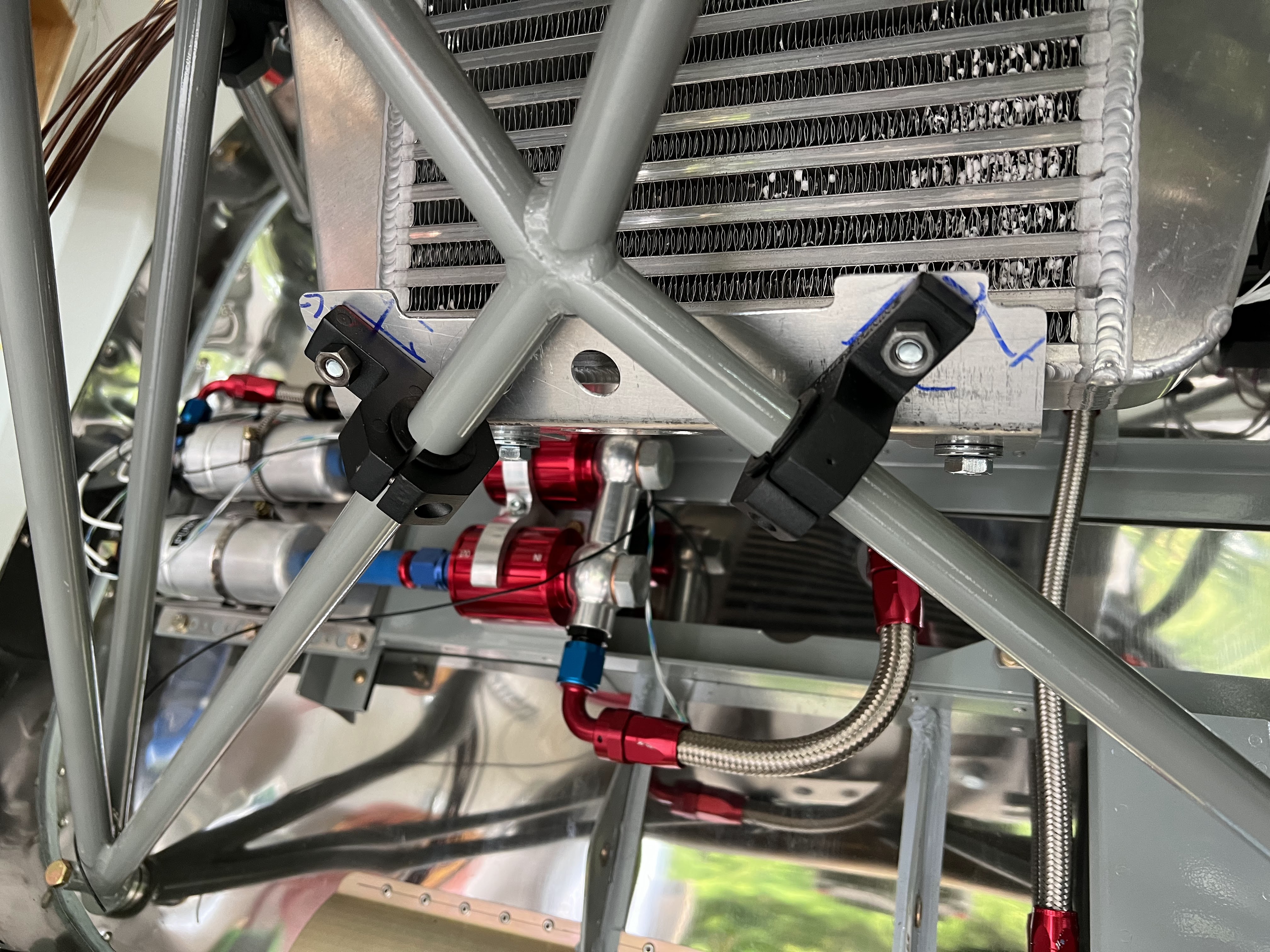
The mounting is nice and stiff. It's not going anywhere, which is the point.
For the outlet of the cooler to the throttle body, I need 3 bends. I also have to reroute the engine umbilical slightly.
I bought 3 90 degree bends and cut them up appropriately, with a 2.5" piece of 2"OD aluminum as a coupler.

Next is the plenum. Goals:
- Light as possible
- ability to remove when installed (I dont have enough room to get both the intercooler and plenum in together without taking off the engine - not enough room) on the cooler.
- Leave room at the back to access the filters, etc
- Flat side pieces for the scat tube inlet. I want the tubing as big as possible - ideally 3"
I know there are so many ways to build a mold. I used MDF (aka particle board). Its strong, straight, easy to work. I'm calling my mold the dog house (for obvious reasons).

My original plan was just to wrap it in packing tape and lay it up. But, I know it will come out better if I properly finish the mold, fill the gaps, paint it, etc. So I am. All filled and ready for sanding.
Using a paint and primer in one... will need a couple coats and sanding.

Next it to build the bracket that will capture the plenum on the intercooler. The one data point I have simply RTV'ed the plenum to the intercooler. That is not my plan.
My plan (hopefully) is to build a bracket that wraps around the intercooler with flanges that captures the plenum. That way its removable.
The starting point for the bracket is to simple mimic the shape of the intercooler. Again, I built the mold out of MDF, cut the fiberglass, coated it with resin and waited... and waited. It never hardened. I took it from a brand new can that I thought was promoted - it was not. So mixed a test batch of 100g and promoted it and activated it, worked fine. So cleaned everything off and tried again.

This is too large and will be cut down to fit, and will have a big hole cut in the middle. Bottom line, this will wrap around and seize the intercooler and have flanges to capture the plenum. Add a dozen or so nutplates and the plenum will be removable. 2 layers of bidirectional glass, with some peel ply on top.

Well, failure. The part wont come off the mold. I tried everything I could think of, and the part and mold are damaged beyond repair. Time for plan B - aluminum. Going to go with the same basic design.
What I did wrong:
- The mold was too strong. There was no way to get the part off. No way to wiggle it out.
- I used wax, and probably should have used mold release.
- Should have made the mold out of foam so I could chip it out.
The big issue seems to be the corners, which are rounded with a 1/2" radius. There is 4 layers of glass on all the corners. Its super strong.
I have wasted about 3 half days on this. Very frustrating.

The layout for the end caps will be the most challenging.


Looks about right. Now just need to drill it.


So it fits in the spot intended and there is enough room to get stuff in and out. The intercooler goes in first and the hoses attached, then the plenum will fit up through the bottom. Attaching it will be a bit of a challenge.
New mount received that is made from 4130. New holes drilled, and mounts tacked in place (forgot to take picture). Now its onto finish welding.
Progress made on the plenum mount for the intercooler.

The plan is a C shaped bracket tha wraps around the intercooler. The holes above are for the intercooler mounts.
After bending. Note: I have to cut a window in the mount for the cooler. Have not gotten to that part yet, but will.

Fit to the intercooler.

Now its onto how to mount the plenum to the bracket (that wraps around the intercooler.
Because of restricted access, I am going to try and make a slot at the bottom that the plenum slots into. The top will just be a flange with nutplates.

All of the bracketry is going to be flush riveted on the bottom, as it has to sit against the cooler. I cant assemble the whole thing together now until its riveted.
After staring at the intercooler bracket and looking at the best way to attach it to the plenum, I decided to make a new one that is slightly larger on the face of the cooler. It just wasnt wide enough to get some flanges installed and have everything tight, so I made a new one that is about an inch wider. To do so, I have to go around the inlet and outlets on the top.

This time I precut the window for the cooler element. I could have cut it after, but much easier to do before its bent.

Fits well. Needs a bit of trimming here and there, but I have enough meat on the sides now to attach some angle brackets / flanges to grab the sides with nutplates.
As a side issue, noticed that the Advanced Flight Systems implementation of the UL CANBUS stack is missing the manifold air temperature. This will be key in assessing the efficiency of the cooler. Feature request submitted to AFS to add this data point. Advanced says 2 to 3 weeks until beta software that includes the feature!
Flanges installed on the new plenum mount.

Upside down view.

The next step will be the intakes for the plenum, and I'm not sure what size yet. This is going to sit now until I get the baffles on, and cowling fitted.