Search This Blog

Sunday, 6 February 2022

Electrical System - Decisions

The two most important systems in this aircraft is the fuel system, and the electrical system.  If something happens to either one, the prop will stop turning.  I have taken a lot of time on these two designs.

All UL power engines are electrically dependant.  If the ECU loses power, the engine will stop turning.  Power to the ECU runs both the computer, and the 2 coils.

There are many designs (and opinions) of how to harden a 12V system with an electrically dependant engine.  The most common is a main / essential bus scenario with 2 batteries.  The essential bus is fed by both batteries for redundancy.  This system can use either 1 or two alternators.  The UL power engine (520T specifically) only has provisions for a single alternator.

Design goals:

  1. Simplicity (within reason).  Needs to be as simple as possible while meeting design goals
  2. Multiple batteries for both redundancy and goal 3.
  3. 1 hour plus runtime in the event of an alternator failure.  6 cylinder UL engine needs 
  4. Start engine from either battery, or both
Failure modes.  The system needs to be resilient against:
  1. Alternator failure (keep engine running for 1 hour minimum)
  2. Device short circuit (protect battery from over discharge)
  3. Over voltage (in case of regulator failure)
Jumping to the end, below is the output of the process:


Capacity Requirements:


Design Process:

Throughout this process, I looked at the following configurations:
  • Option A:  Two independant batteries, 1 bus, 1 alternator
  • Option B:  Main / Essential bus, 1 battery per bus, 1 alternator
  • Option C:  EFII Bus Manager (Main / Essential bus, 1 battery per bus, 1 alternator)
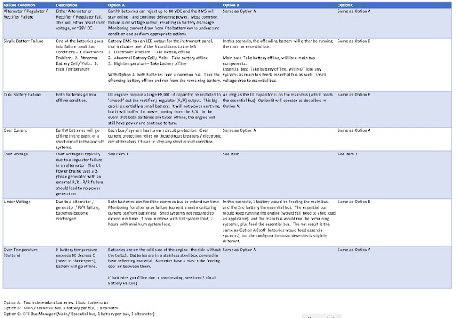
Below is a table of each option and how it should react in a specific failure condition.


So after months of research, discussions and pondering I am going with option A.
  • Simpler
  • No diode loss
  • All systems can be run of either battery, or both
  • Unlike standard lead acid or AGM batteries, the EarthX have their own monitoring - in theory you know what is happening
  • With the UL system (permanent magnet generator, not an alternator requiring voltage to excite the field coil) you can run without batteries (if capacitor installed on bus side).  In the event of complete battery failures, the engine will still run.
  • EarthX has built in over voltage rejection
  • Does require more manual intervention... pilot will have to monitor battery status, charge current / generator status, etc.  

Wednesday, 2 February 2022

Firewall - Part I

The partially completed fuselage kit I bought already had the firewall roughed out, along with all the brackets that tie the firewall to the fuselage.  Step 1 was to see how it fits...


Luckily, it fits very nicely :-)

Because I am not going with a 'standard' engine, I need to do a lot of stuff that is not in the book.  So I have been planning out where I am going to put everything.

Stuff to fit:

  • Batteries (including capacitors needed for UL install)
  • Voltage regulator (50A)
  • Gascolator
  • Fuel pumps / filters
  • Primary fuel feed / fuel injection return
  • Air / oil separator
  • Cabin heat box
  • Throttle, and cabin heat controls
  • Master relay(s) (do not need starter relay, as it is on the engine)
  • MAP sensor
  • Fuel pressure sensor (which is fitting to output of fine fuel filter, via banjo fitting)

In order to 'fit' everything, I had a local plexiglass shop make me a Plexiglas firewall.  They cut the outside profile of the firewall, and the slots that go around the nose gear mount.

I am not comfortable with the limited amount of hard points on the cage for attaching accessories.  So during this process, I am going to add a number of additional hard points.

My kit did not come with the material needed for the angle structure that goes on the firewall, so I ordered a bunch of 1.25 x 1.25 x 0.125 6061 T6 angle.

The Glasair documentation for anything firewall forward is very lacking... once I got over that and figured I am on my own, it started moving much quicker.  A lot of hunting and frustration was involved trying to figure out what to do.


Firewall Framework:  Glasair uses an aluminum angle structure (attached to hard points on the cage) to mount all accessories.  In a 'usual' Sportsman, this would include battery, oil cooler, engine transducers, firewall pass throughs for wiring, cabin heat box, etc.

Goal:  Have ZERO firewall penetrations that need to be removed.  Example:  Battery mounting - the goal will be to be able to remove the battery without having to remove a firewall penetration.  This will apply to everything.  Coils, fuel filters, regulator, etc.  Once the firewall and framework is mounted, nothing will need to be removed EVER.

With using a UL Power Engine, my needs are a bit different:
  1. (Electric) Fuel pumps (qty 2 - primary and backup, controlled by the ECU)
  2. Fuel filters (course and fine)
  3. Air / oil separator
  4. Gascolator
  5. Batteries (qty 2 - EarthX ETX900)
  6. Coil packs (qty 2)
  7. Master relays (qty 2 - one for each battery)
  8. Cabin heat box (stainless - Canadian requirement)
  9. Main fuel line (output from either pumps or header)
  10. Fuel injector return
Fuel Pumps / Fine Filters - Location (Note - also see Fuel System post for more details (add link)):  Option 1 will be to put the pumps on the forward tunnel inside the cockpit.  Option 2 is on the firewall.  Honestly, I don't like either option, but they have to go somewhere.  All of the hardware is ordered to adapt the standard UL pumps / filters to inline input and output rather than side entry.  With all this, it should fit in the tunnel.  If that doesn't work, then I will come back to putting all this stuff on the firewall.

I am pushing ahead with plan A - filters / pumps under the header, on top of the forward tunnel.  Something like this:


Tentative tank placement:


The firewall framework has been proceeding well.  Mounts made for coil packs, regulator, fuel filter, batteries, gascolator, etc.


Once the pump and filters are complete, then I can proceed to putting in the Plexiglas template and fitting the cabin heat box, cable passthroughs, air deflector, etc.  Hopefully then I can really start moving.

Plexi firewall in place.  Main fuel line drilled, as well as return.  Cabin heat airbox next.  Battery box clamped in place.


A lot of the above did not work out:
  • Battery box too wide and too low - hit engine mount (I finally had the brainwave I had better put it on and check for clearance issues...)
  • Gascolator not low enough.  Hit exit ramp that transitions between the bottom of the fuselage and firewall.
So I changed my mind on the battery box.  Decided to go stainless, and cover it in a reflective mat.  From reading on the forum, this seems to be a good option.  I will also put a 1" cooling flange on the front.

Redesigned the gascolator mount to be similar to the Glasair design (I am using the same Gascolator they use).


5 pieces to the battery box.  
  1. Floor the rivets from the bottom
  2. Back mount that will tie into the firewall structure on both sides.
  3. Front cover that wraps around to tie the back mount and floor together
  4. Strap that hold the batteries in.
To pull the batteries will require taking the box off, but it will only be 5 bolts (plus the wires) and the entire box comes out.

Firewall frame below removed for drilling / finishing.  The back is flush riveted so it won't interfere with the firewall.


Firewall frame all primed, relays temporarily mounted, gasolator fit checked, cabin heat box drilled.


Parts getting their grey coating to match the engine mount (and everything else)


Exit air ramp drilled.  The bottom is held in with captive fasteners on the bottom of the firewall stainless.  Screws will go through the fiberglass, air ramp, and then into the firewall structure.


Everything completed to date installed.  (New) plan is to finish all the cockpit / avionics wiring with the firewall out.  Real firewall will not be installed until after engine / engine mount has been test fit.

The firewall template has been out of the fuselage for a month or more while working on other things.  Its pretty much going to stay in this state until I have an engine.  Part II will cover the next phase of the firewall later in 2022.

Instrument Panel - Part I

This will be a long post, written over many months... 

I have built one instrument panel in the past, and honestly learned a lot.  Both what works, and what doesn't work.  That experience will serve me well (I hope).

Here are the decisions that need to be made:

  1. What is the mission? (IFR / VFR)
  2. Discrete instruments, or system
  3. Tentatively select components
  4. Determine real estate - how much room is there to work with.
  5. Do initial layout, and determine roughly what goes where.  
  6. Test run.  Sit in airplane with panel blank, with paper instruments.  Its amazing what looks good on paper will not work when you are actually sitting in the airplane
  7. Refine design, incorporate changes from test run.
  8. Do actual mechanical layout.
  9. Wiring diagram / wire run list (pin to pin wiring table)
  10. Make panel inserts / structure
  11. Assemble / wire
  12. Configure / test
The first two answers are relatively easy.

  1. Mission:  IFR.  I do not have my IFR ticket yet, but my plan is to do it once the Sportsman is complete.  At a minimum, I will wire everything but may not purchase a few components right away due to cost.
  2. Discrete Instruments or System:  System.  Currently planning on Dynon.  I have Dynon is the Emeraude.  They are 2 hours down the I-5, are super awesome at tech support and returns.  All the pricing is pretty much the same.  The big game changer is their Advanced Control Module that makes wiring way easier.  The downside is they do not have a diversity transponder option, and do not support the uAvionix TailbeaconX.

Version 1.0 design


This is the end state... may take a couple phases to get here, but this is the goal - or at least something close to this.

This week I talked to Advanced Flight Systems and received a quote for their 'quick panel'.  Honestly, I am struggling with the price a bit - not of the components, but for the ACM, wiring, and metal work.  Its like $9500 USD for those 3 components.  If you take out the ACM, its like 7K.  I can build a lot of stuff for 7K.  But on the flip side, its comes with all the documentation, panels are cut, painted, labeled, all wiring, switches, tested and ready to go.  I can build a lot of stuff if I don't take 3 months to design and build a panel.

UPDATE:  I worked the math and took into account the cost of the wire, switches, cutting, painting, labeling, etc and the cost differential goes to like $3600.  This makes a lot more sense.

First piece of metal cut for the avionics... accessory tray!


One of the big attractions to Dynon / AFS is their ACM (Advanced Control Module).  It is the main wiring hub for the aircraft (except critical Engine wiring).  Aides in wiring, troubleshooting, and future upgrades.  On the downside, it is a single point of failure...  But the architecture lends itself to not completely failing.  It also has connections to a backup battery, that will keep the displays running.

Version 2 of the design is below... based on the AF-5600T.


Many changes from V1.  Probably a few more versions to go...  But I am getting closer. Plan is to order after Oshkosh 2021 - after seeing what is new / on special.

The only compromise I have made so far is the fuel gauge for the header tank.  AFS (and Dynon for that matter) only support 4 tanks.  AFS does not have any other input I can repurpose.  But, with that said all I really care about is knowing if it is not full, or getting low.  My plan was to put a capacitive probe in from the top down... I even bought the mounting flange.

Belite / Radiant makes an ultrasonic fuel sensor that mounts to the outside of the tank (no hole or fitting required - its bonded in place) that tells you if there is liquid there or not.  They have 2 versions - one that works with their fuel gauge / computer, and one that has stand alone indicators.  They have other ultrasonic senders that will give you quantity, but I don't have room for their gauge in the current layout.

https://radiantinstruments.com/bingo-4-liquid-detector/

My plan is to put 2 of their sensors in.  One at 1/3rd tank, and one at 2/3rds.  Green LED means good, red means bad.  I think this fits the bill.

I thought about just putting a sight gauge in... but the top would be out of your field of view... in fact you would barely be able to see any of it.  I think the sensor idea is a better solution.

Panel ordered from AFS on Tue, Aug 3 2021.  ~4 month delivery.

Final panel design received from Advanced on Thu, Nov 1.  


Very similar to my original design.  Took 3 revs to get it perfect.  The 3rd rev was text and hole alignment.  It certainly does pay to have a design in mind when having it built.

Now its cutting metal, finishing, and wiring...  hopefully will have everything by Xmas.

Below pic is from Advanced.  They just received all the metal parts back from powder coat.


Fitting the panel:


The instrument panel comes with pre-drilled holes that should line up with the horizontal tabs on the cage.  They do not.  To get it centered, it needs to shift to the left about 0.5".  Asking Glasair and the forum for advice.  Daniel Lodge on the forum recommended filling the unused holes, and putting a layer of glass overtop. That will be on the agenda for when everything comes out.  I have some black pigment for resin coming, so it wont look to awful.

Today (Jan 14, 2022), Advanced sent me a picture of the panel assembled and mainly functional (missing switches).  So very cool to see what is coming soon.  Hopefully next week.


Jan 31, 2022:  Panel is ready.  Picking up from AFS on Fri, Feb 4.  

Part II and III will cover the installation, wiring and testing.


Saturday, 22 January 2022

Rear Seats

 Glasair offers a rear seat kit.  $5K with no upholstery.  Luckily I have gotten some pics of the rear seat assembly and am going to 'roll my own'.

There are two horizontal tubes that attach to the vertical uprights on both sides that anchor the seat back.  The seat bottoms are fastened to the back via a piano hinge, and lift up for storage.  The cable / wiring tunnel has two brackets that the seat bottom rests on the INNER side, and then there are two outboard portions that are fiberglass and foam.

Plan of attack:

  1. Build upper and lower attach brackets to the cage
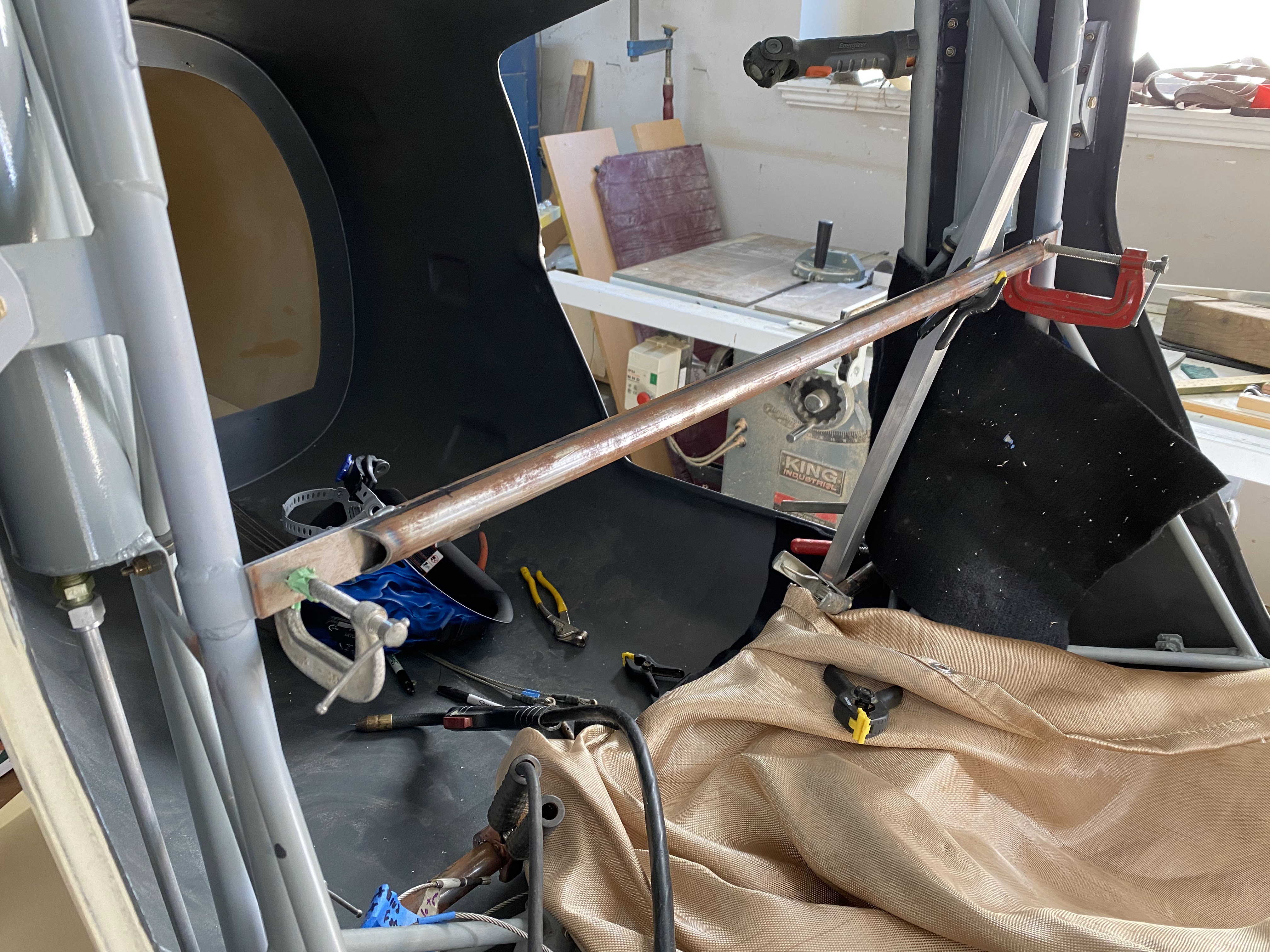
  2. Fabricate horizontal tubes that tie the cage uprights together.
  3. Fabricate the seat backs and bottoms
    1. Foam and Fiberglass
  4. Form the tunnel and outboard sections
    1. Aluminum
  5. Buy the bulkhead from Glasair (ordered)
  6. Fabricate the composite L brackets that the centre tunnel attaches to
  7. Finishing
  8. Bolt / rivet it all together.
  9. Upholstery (in combination with the front seats)
Cage Attach Brackets

The upper location is determined by the cutout in the truss cover on the forward upright.  The bottom bracket is 16.75" centre to centre from the top, but on the aft upright.


I used weld through primer on the back of the brackets and cage where you can't get paint.  I left the brackets long, and have not drilled them yet.


Cross tubes cut and tabs rough fit.  Seat back tabs in process.  Next is rear seat headrest mounts.


A fellow builder gave me dimensions for the placement of the rear bulkhead, and anything else I could not easily determine.

Measurements for the bulkhead measured from bulkhead A to the rear seat bulkhead
Bulkhead A to the bottom aft edge 30 1/4”
Bulkhead A to the top aft edge 29 5/8”
The bulkhead is angled back


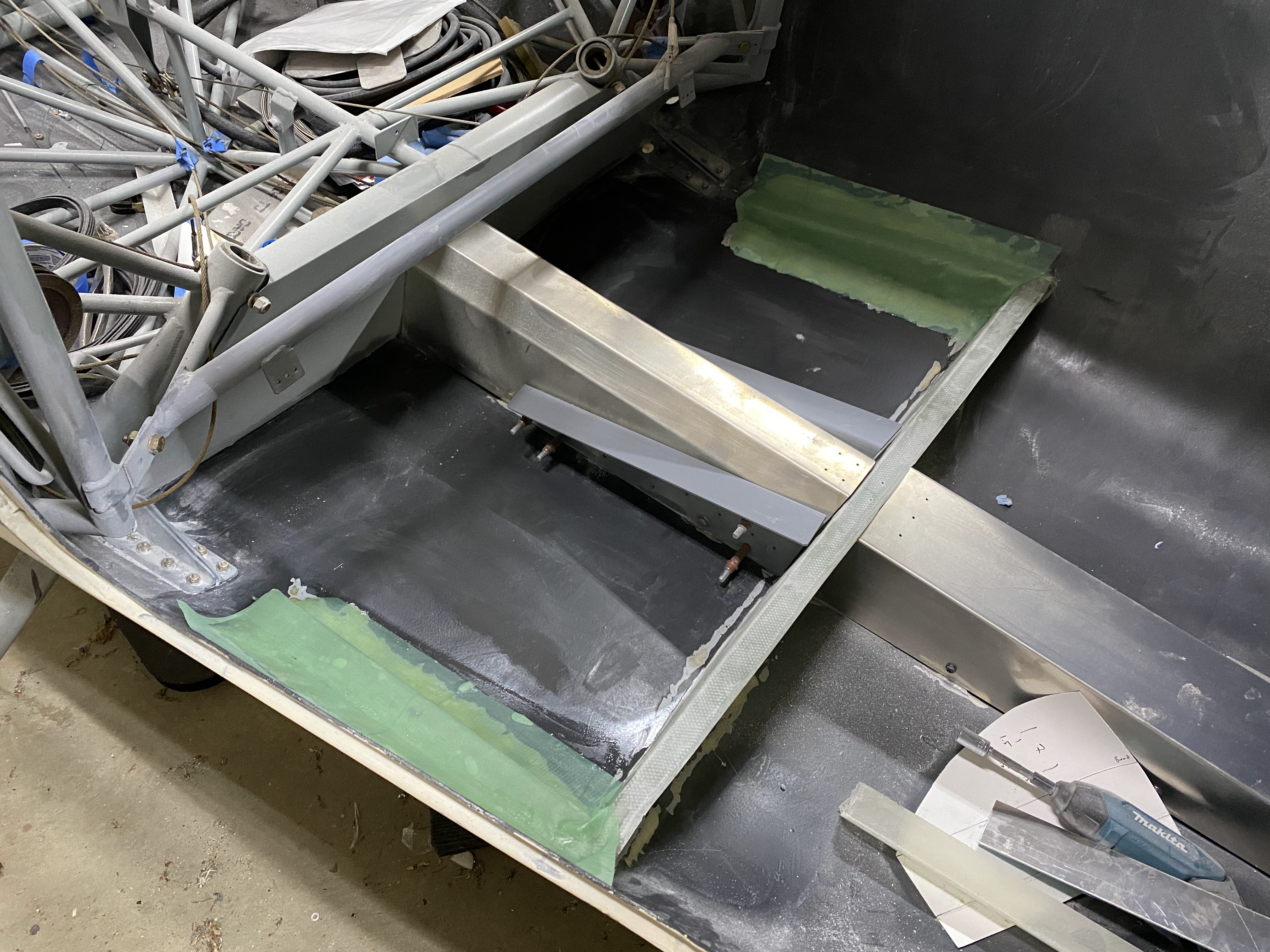
Once I had the bulkhead placed, I marked it in key areas, then used aluminum tape on the entire area, then sanded down until I hit fiberglass.

The below drawings are not super high quality, but are close.  They needed a bit of trimming after the fact.


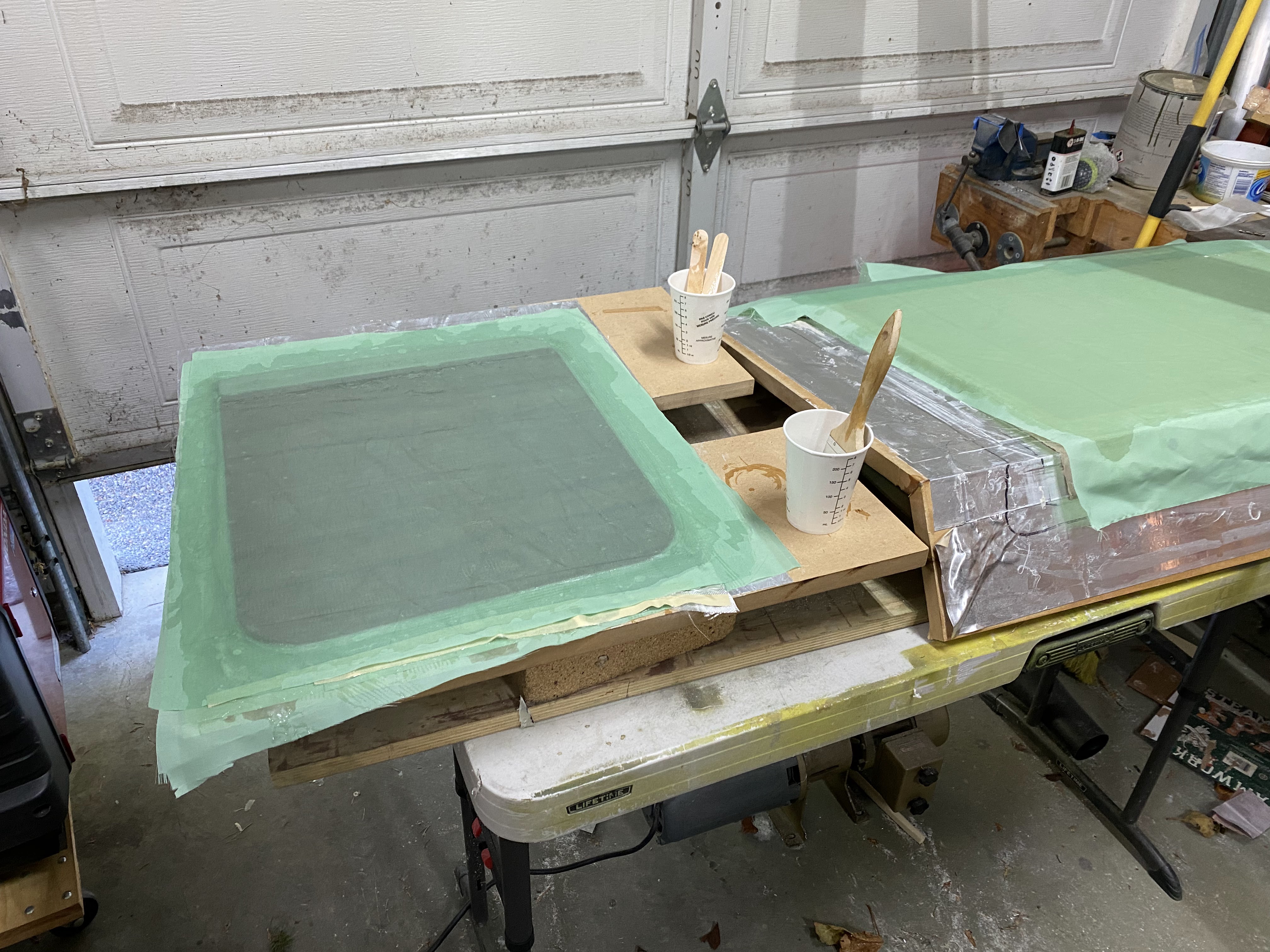
Next is the composite angles for mounting the covers.  I made angles using 2 pieces of MDF screwed together at 90 degrees, then covering with packing tape.  6 layers of cloth, with peel ply on top.  Then I ran them through the table saw to get rid of the bad edges, then cut into 1.5" pieces.  I went wider than how Glasair does it as I want room to put a either an 8-32 or 10-32 nut plate.  I really dislike the self taping screws that GA uses.


Forward and aft tunnel covers needed a fair bit of tweaking.  One of them turned out to be a throw a way.  But they fit!


The covers are attached at the bulkhead with a screw in the Glasair design.  I am putting 2 in for good measure.  Each cover has a tab that ties them together.

Mounting the inner seat rails was interesting.  I sketched out the sides with them in place, then drilled through on the mounting holes to double check.  Then went back and drilled about another 15 holes per side to rivet them together.


Next step is foot rests.

In the Glasair design, the footrests mount over top of the aft cover.  So to get the cover off, you have to take out the foot rests.  I am going to try and invert that so you can get the cover out without removing the foot rests.  


Finishing


Rear Seat Foot Rests

While I don't really grasp what exactly these are for (except keeping a rear facing passengers feet off bulkhead A), they do serve a purpose in hiding the wiring going aft, and keeping it out of the way of the control cables.

Made a paper mock up that is similar to the Glasair design.


Turned this into .040 aluminum, and then reversed the template for the other side.


The two sides are not quite symmetrical... probably because the tunnel is not perfectly centred, or the tabs are not perfectly centred.

The stock Glasair design requires that the footrests come out the remove the tunnel.  I am changing that so they are independent.  There will be a plate that ties the footrests together along with the tunnel, but it will be removed with the tunnel and tied in with screws.  That is the theory at least...

Seat back:

The seat back attached to the two tubes shown below.  It is one piece, and wraps on top of the top tube, and then drops straight down.

The angle from the seat back to the top flat piece is 75 degrees.  From the seat back after the bottom tube in transitions down at 15 degrees.

Below is what a finished setback looks like...


So after a lot of figuring, I decided to make a mold.  The foam will be cut and laid on the mold, and the whole thing will be bagged.

Making the mold out of leftover MDF from the tops of my wing jigs.  Cutting the angles on the mold on the table saw, and then gluing it together


Gluing the top piece on.  The bottom (in the picture that you cant see) was taped together with it laying flat with 4" wide aluminum tape, and pressed down with a wallpaper roller.  Put epoxy in the slot, pull it up and tape it in place.

Same process for the bottom piece, but used ratchet straps.


The foam that came with the kit is not big enough.  I added onto it by epoxy with tape lying on a flat surface.


Top piece of foam added (glued) using the form as, well, a form.  Waxed the bottom and clamped the top in place while it set.  

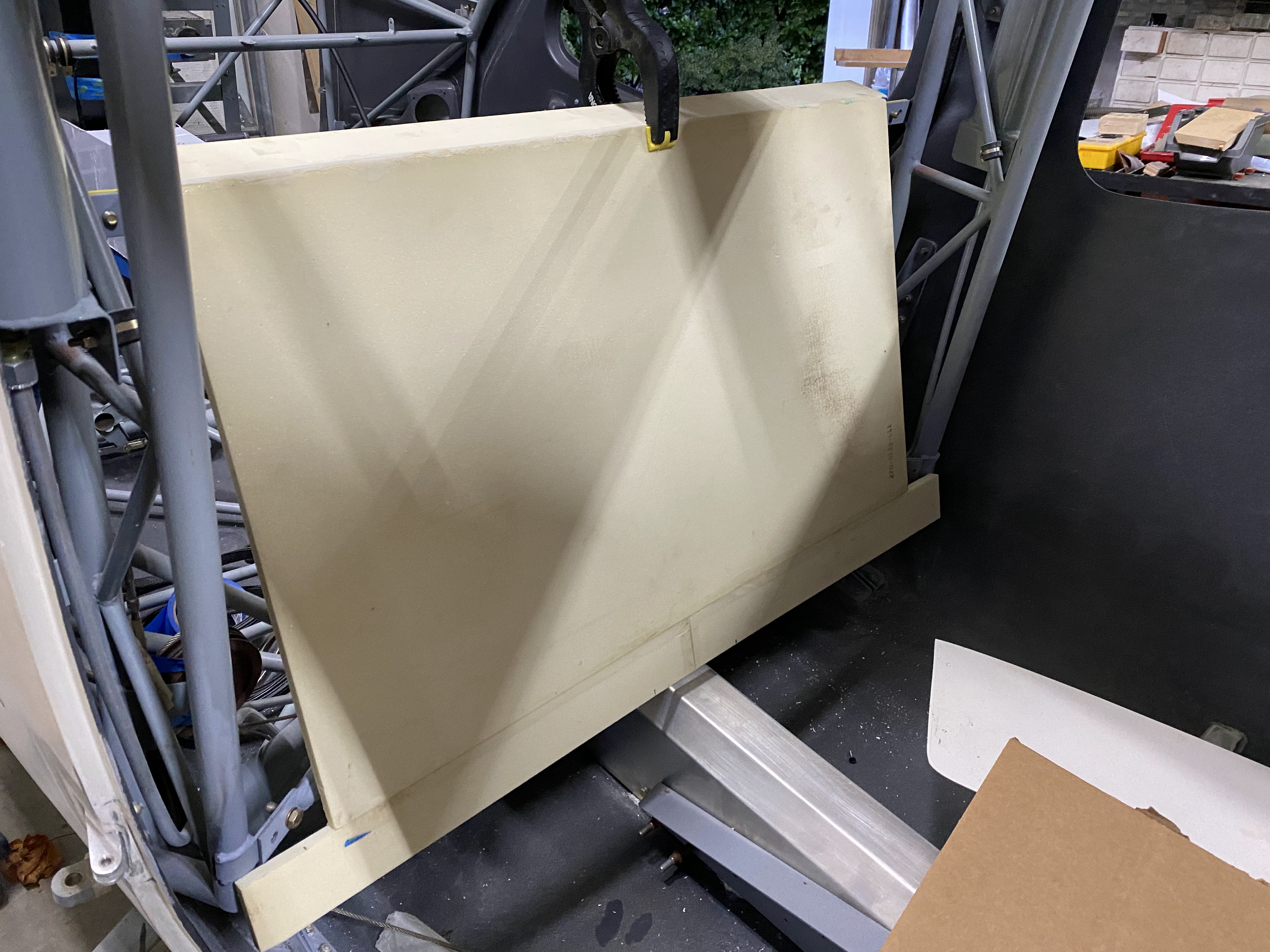
Clamped in place for first fit...


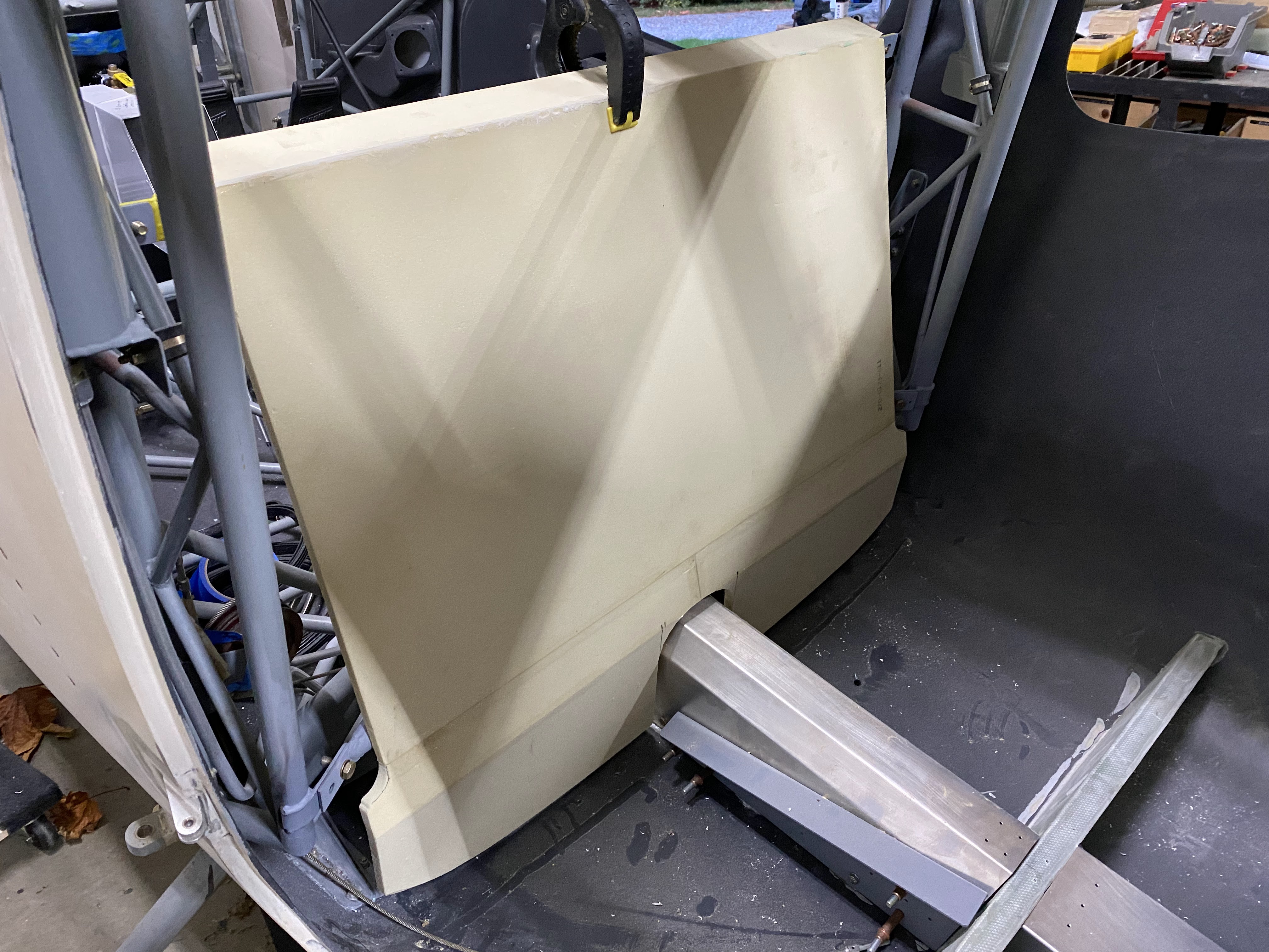
Added the lower portion of the setback, and cut the notch around the centre tunnel.


Cut the bottom contour and clamped in place temporarily.


Next will be lots of sanding to contour the corners and edges, plus filling any gaps...


Next is making the aluminum plates that the piano hinges will attach to.  Two sets of piano hinges... one for the seat bottoms, and one for the baggage floor.... more on that later.

Composite angles / outer seat bottom rails.

The inner seat rails are aluminum, and riveted (or will be) to the centre tunnel.  The outer rails are composite, and there are two methods.  Foam block with fibreglass on top, or composite angles.  I went the composite angles route.

The angles where formed using an MDF L bracket, covered with packing tape and wax.  4 layers of glass laid down, with peel ply on top.  Then ripped on the table saw to dimensions.  This is how I made all the angles for the tunnel covers and overhead cable cover.  Super strong, works well.

Lots of fitting takes place, as nothing is square.  Once I got them to fit, marked the outlines and sanded off the paint on the fuselage, then bonded the angles in place with a resin, cabosil and glass fibre mixture.  That is the picture below...


The peel ply just smooths out the bumps and leaves a nice finish I can glass on top of.

Next will be 2 layers of glass on top of the composite angles to bond them in place.


Getting the backboard ready to go.  Aluminum plates are bonded in the bottom for the piano hinge rivets to have something to bite into.


Then everything is laid up.  From the bottom:
  • Waxed mold
  • Peel ply
  • 2 layers of glass
  • Foam
  • Peel ply
  • Perforated sheet
  • Bleeder
  • Bag

The layup took over an hour going as fast as I could.  Tomorrow will be the day of truth to see how well it worked.


After lots of filling and sanding, its getting close.  Going to put an additional layer of glass on the top surface.  The seat bottoms are thing plywood that I am going to layup with 2 layers of glass top and bottom, plus an aluminum plate to rivet the hinges to.


The footrests are drilled and tied to bulkhead A.  This really stiffened up the rear tunnel cover.


First seat bottom layup.


Seat back after many hours of filling / sanding.  Almost done.  It is sprayed with FlexFill in this pic.  Really does a nice job with all the really small imperfections.


Final fit of the seatback with actual hardware in place.  Fits exactly like it should.

Next step is hinges for the seat bottoms, and repair the fuselage paint.

While waiting for everything to dry, I started the seatbelt mounts.  The outer ones are easy... they just tie into the existing cage-to-fuselage mounts.  The inner ones are a bit more.


Once the holes were drilled, and the foam between the glass removed, the bottom of the fuselage was taped and I used a syringe to get the epoxy / microballoons into the holes.  Seems to have worked out good.


Seat back installed and initial hinge drilling.

Hinges installed.  Last step is the seat belt mounts.


I actually hopped in and sat in the seat.  Its actually roomy for my 6'2" frame.

Seat belt brackets are in, but not tightened down.  They are going to have to be removed for paint / wrap anyway.


These rear seats were a lot of work.  The tubing and welding started in July (along with the header tank tabs, battery tabs, etc).  In September I started to figure out the vacuum bagging process, and designed / made all the rear tunnel covers, bonded in the fiberglass bulkhead, and did all the mounting tabs.  October was the foot rests, and how I was going to mount them.  In November I started on the composite backrest, along with the outboard seat bottom mounts, along with the actual seat bottoms.  December was filling, sanding and finishing.  Riveting in January.

This was not all back to back, worked on many other things alongside.

This one is done for now until I start upholstery.