Search This Blog

Monday, 16 May 2022

TailBeaconX

The uAvionix TailBeaconX is a very cool little beast.  Has its own GPS, mode S transponder, and ADSB in and out.  Oh, and a light...

AND, its supported by the AFS-5600, so you can drive it from the PFD and MFD.

The wiring is pretty simple.  Power, ground, RS232 TX and RX.

In my case, I am mounting it inside the fuselage about 12" behind bulkhead A.  The mounting bracket and unit weigh less than half a pound.  The wiring weighs the same, if not more.

Other than the fact that when I wired it I mixed up the TX and RX lines, it worked right away.

The TailBeaconX is configured through wifi.  There is an app for your smartphone, and you set everything up through that.

Using the app should be straightforward, and once you follow this process it does work.  Took me awhile to find it.

Advanced already setup the PFD and MFD to talk to it, you just have to initialize it through the Set->Admin>Transponder menu.

Unfortunately our house has foil in the roof, and is stucco.  Basically a faraday cage.  No traffic being shown, but one day I will push it outside and see what I can see.


So after some fussing about, I realized that the TailBeaconX only does ADSB-OUT - not IN.  That is fine, since I have a separate dual band ADSB receiver from Dynon.

Mounting... simple fiberglass bracket bonded just behind bulkhead A.


The transponder and mounting bracket weigh 5.25 oz.

Installed, wired and configured...


Still need to secure the wires, but the mounts are already in place (and epoxied in).


Dont know if it is actually working or not, but it seems to be.

One really important note:  Some of the configuration needs to happen on the tail beacon.  This is done through the build in wifi access point in the TBx itself.  You can only configure it when the transponder is in standby - which makes sense.  I was trying to verify the configuration and had the transponder 'ON" on the EFIS.... uAvionix support figured that out really fast.

Super cool technology.


Miscellaneous 'STUFF'

Have been diligently working away on a number of items.  So this is a real grab bag of things that are underway.

Headset Jacks

In my package from Advanced, I received a harness for all of the audio jacks.  4 phones, 4 mics, plus a hardwired music input.  I did tell them how long to make it :-).

I was debating on where to put the jacks.  There were a number of options:

  1. Overhead cable cover (right behind the pilot / copilot's heads)
  2. Overhead console (from Fibertech composites).  I have my tailwheel lock and light installed in here.  Could use the sides, but they are not terribly strong.
So after a bunch of debate I decided to put them where Glasair does.... in the aft center of the cable cover.  Most just drill holes and seat the jacks.  I decided to get a nice little engraved and painted plate to mount there.

I had been looking for an excuse to try Front Panel Express. They have their own design software, and give you a price.  Below is my final design using their software.


For small stuff, you can print to scale.  Below is a previous version of the design that I printed and checked.


I ordered the plate on a Friday afternoon.  It shipped the next Tuesday (I ordered 5 business day turn around, but they shipped it in 2).  Delivered Wednesday.

Cost:  $88 USD, $96 with Tax.  Shipping included.

Once received I cut the hole in the cover.  The panel will fit through the hole sideways if needed for future removal.

To secure the wiring, I took some standard plastic tie wrap mounts and ground off the sticky backing.  Took as much off as I could with a knife first, then use the belt sander on the rest.  Then I epoxied the mounts to the inside of the cover after sanding and cleaning the target area.

Then it was just tie wrapping the harness in place (taking note to ensure that the cables will not rub).


The cover easily slipped in place.

The harness is then tie wrapped to the vertical risers on the aft side (again, keeping them away from the cables).


Previously I had cut, fit and finished the overhead console that houses the cabin light and tailwheel lock.  Need to wire it...  

The ACM has an output for cabin lighting, that can either be 'always on' or switched.  I am going for the always on option.  2x22 gauge wires run along the upper beam and tie wrapped.  There is a 2 position connector inside the overhead console for easy disconnect if / when needed.  Have not terminated on the ACM yet, but that will be soon enough.

Temporarily wired to a 12 power supply to check connections.


Lastly, I finally decided to ditch the trike gear legs (ditch = remove from fuselage).  I had been leaving them on as it make removing the main gear legs super easy.  All the final hardware is installed on the main gear legs, so it was time.


Back to wiring... going to work on the rear first.  Belly strobe, elevator trim, etc.  Ordered all the RG400 I am going to need, so will get that soon hopefully.


Monday, 4 April 2022

Instrument Panel - Part II (initial mounting of components)

Yesterday (Fri, Feb 4) I picked up my panel / avionics from Advanced in Canby, OR.  Nice 1100KM round trip single day...

The folks at Advanced were excellent.  Dove into any question, and if someone didn't have an answer they went and found who did.  


We went through every item line by line, then boxed it all.  There is so little metal left in the panel that it is very floppy, and will be until it is mounted into the carbon fibre shell.

Next task is cutting the carbon shell.  I am not looking forward to this...


Plan is to drill all the mounting holes first, then with everything clecoed in place mark the edges of what needs to be cut.  Then mark out a real cut line, drill the corners, and then go at the straight pieces with a Dremel with a diamond bit.


After first batch of cuts...  Carbon fibre is way itchier then fiberglass.


When I started drilling for fasteners, the clear on top of the carbon started to lift in some areas.  Some parts of the panel are fine, some its just flaking off in chunks.  


I put a support request in with the factory, and had a phone call that same day.  Prep (or lack thereof) is the most likely culprit.  Once I finish all the cutting / drilling / fasteners Glasair is going to re-clear it.  I just have to get it to them.  Very impressed with the support.

I took a break from the panel for a bit and started chewing on where am I going to put the ACM.  My original plan was a stand alone shelf on the pilots side, forward of the pilot and panel crossbar.  However, there was a post on the forum where another builder fabricated a large-ish shelf.  I think I am going to explore this option and see how it works out.


The nice thing about the shelf concept is I will have LOTS of room for all the boxes... of which there are many.

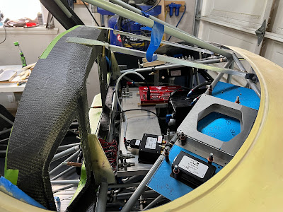
Below is a very crude drawing of all the avionics placement looking from the top down.  For the left and right side trays, components are mounted both on the top and bottom.


Note:  The gap between the header and panel / ACM and ADAHRS's is for future IFR expansion.  This is where the Garmin 255 and Avidyne 410 will go (eventually...)

Boxes to mount forward of the panel.  This is a working list and will probably change slightly.  But bottom line I need real estate, and the shelf gets me there quite quickly.  If the shelf works out, I plan on migrating the ECU and boost controller to the shelf.  The capacitor is moving to the firewall.

ItemDescriptionQuantityProposed locationDimensions
AF5000 backup batteryLeft shelf - under
ADAHRS-200Primary ADAHRS1Center shelf - right4.71" x 2.61" x 1.22"
ADAHRS-200Backup ADAHRS1Center shelf - right4.71" x 2.61" x 1.22"
EMS-221 Canbus Engine ModuleAdvanced Canbus Module - to talk to UL ECU1Center shelf - right6.35" X 2.99" x 1.09"
ADSB-472Skyview ADSB 472 Dual band 1Right shelf - top4" x 2.79" x 0.97"
GPS-2020ADS-B 2020 GPS Receiver Module1Left shelf - top
PDA360XRRemote Audio Panel1Right shelf - under7.64" x 5.82" x 1.34"
ACMAdvanced Control Module1Center shelf - right9.94" x 6.85" x 0.88"
Shunt60A Ammeter shunt1Right shelf - top5.9" x 1.96" x 1.18"
UL ECUUL Power Engine Control Unit1Center shelf - right5.2" x 4.25" x ?
UL Boost ControllerUL Power Boost Controller1Center shelf - right1.53" x 2.56" x ?
Cockpit Ground BlockGround block inside the avionics section1Left shelf - top6.4375" x .9375" x 1.03"
TCW Backup Battery6AH battery backup for Avionics (not engine)Left shelf - under7.7" x 2.29" x 2.75"

I think the shelf concept is going to work... I widened the cutout for the header tank to starboard so it can be removed and installed with the shelf and all the avionics in place.

I have everything temporary mounted EXCEPT the ECU and boost controller (because I don't have them yet).


Finished cutting the carbon out of the panel.  Working on Nutplates.... lots and lots and lots of Nutplates.


There are 4 problem locations.  There are vertical tabs on the back of the panel that sit on the crossbar.  3 of the holes needed for mounting the aluminum inserts are interfering and will require some creative solutions.

Also, in my crazy desire for fancy lit switches (and lots of switches) there is no room to mount the Nutplates for the two switch mounting plates.  So again, going to have to get creative.  

So after lots of noodling, I came up with a plan to make a small thick (0.1") aluminum plate the nestles into the corners.  The Nutplates are attached it the plate, and then the plates are riveted / bonded in place.  This will keep all the rivets hidden.


The switch panels fit exactly like they should... 


I lost track how many Nutplates are in the panel, but it has to be over 30.  Each nut plate requires 6 drilling / countersinking operations, plus clecoing and riveting.  I found the idea of a template from Glasair (it was in one of their TWTT manuals).


I have a bunch of these for different sizes of nutplate.  They are made of steel (whatever you have lying around).  Eventually they wear out, then you throw it away and make another one.  I found a few scraps of hardened steel and I use that for the ones that most often used (#8 and #10 standard 2 leg nut plates).

Next is mounting the angles for the future GNC255 NAV/COM and the Avidyne 410 navigator.  After consulting with our local avionics 'expert', the gap between the angles needs to be 6.35".  I have already cut and bent the angles... now I have to figure out how to mount them EXACTLY parallel to each other.  2 issues... the cover plate that hides the hole also hides the mounting holes.  So you can't have the brackets installed and the cover plate.  No big deal... these brackets are all drilled, filed, painted and fasteners installed.


I had to put everything together to get a good look at it.  I am very happy...

TailbeaconX / transponder:  This thing is super small and super light.  I am opting to put it in the fuselage since the Sportsman does not have a tail light, and also because it is relatively fragile.

To make the mounting bracket I went overboard.  Layed up 3 layers of glass on the outside of the fuselage to get the curve (which is so slight across 3" I shouldn't not have bothered).  The mounting flange is a chunk of 6 layer glass that I had laying around.  I drilled fitted the TBx, then bonded it to the mount plate.  When that was done, 2 small layers on each side of the flange and it is super strong.  Mounted all the hardware, then bonded the whole thing to the inner fuselage.


The entire Tailbeacon (including the mounting flange) only weighs 5.25 oz (155 grams).  That is insane...


The GPS comes unterminated... now terminated.

That's it for now.  Wiring is next.


Friday, 1 April 2022

Extended Heavy Duty Main Gear - Part II

The gear legs have been to the powder coaters, and are installed back on the fuselage.

I have been debating for awhile how to jack the plane once fully assembled.  The issue:

  • The Sportsman (or any rod type spring gear) have no natural spot to jack a wheel.
  • Bushtires just make it worse.  I have the bolt on axles, which gives you a small amount of area to jack on, which is gone with the big tires.
Many folks have been using a jack pad which is bolted onto the inside of the gear leg (same holes as the axle).  This will work for me, but I have to make it super wide in order to actually grab onto it with a floor jack.

The plan is to start with some 4"x4"x0.25" 6061 Aluminum L stock.

Angle:  With the bush tires, the sportsman sits very nose high.  I calculated the angle needed on the bracket to be parallel with the ground and came up with 23 degrees.  I checked on the forum, and 22 degrees is the number...


Here is the first one rough cut and assembled just to check for any interference issues.  It even lifts the plane (no wings, no engine, partial interior, partial panel), but a 2x4 is needed as my floor jack is not tall enough.  Need to finish this one, and then build a mirror image.

I can already hear people asking "what is that for...???".

Both brackets roughed out, ready to head for welding.


Brackets welded and cleaned up.


Per Ted's suggestion, I put a couple AN-4 threaded holes on the 'foot'.  Ted uses these so the jack won't slip off.  I am planning on using them to mount a hockey puck for the jack to sit on.  At least that is the plan.... 

All primed and ready for paint.


Prior to painting, I ran them through AlumiPrep and Alodine, then primed them.


Finished product.  The puck is to protect the finish, stop it from slipping off the jack, and to allow the jack to be a bit shorter.  They are temporary... put them in when needed, and remove when not.  2 x AN4 bolts through the bottom.  Can be installed and removed in less than a minute.

Sunday, 6 February 2022

Electrical System - Decisions

The two most important systems in this aircraft is the fuel system, and the electrical system.  If something happens to either one, the prop will stop turning.  I have taken a lot of time on these two designs.

All UL power engines are electrically dependant.  If the ECU loses power, the engine will stop turning.  Power to the ECU runs both the computer, and the 2 coils.

There are many designs (and opinions) of how to harden a 12V system with an electrically dependant engine.  The most common is a main / essential bus scenario with 2 batteries.  The essential bus is fed by both batteries for redundancy.  This system can use either 1 or two alternators.  The UL power engine (520T specifically) only has provisions for a single alternator.

Design goals:

  1. Simplicity (within reason).  Needs to be as simple as possible while meeting design goals
  2. Multiple batteries for both redundancy and goal 3.
  3. 1 hour plus runtime in the event of an alternator failure.  6 cylinder UL engine needs 
  4. Start engine from either battery, or both
Failure modes.  The system needs to be resilient against:
  1. Alternator failure (keep engine running for 1 hour minimum)
  2. Device short circuit (protect battery from over discharge)
  3. Over voltage (in case of regulator failure)
Jumping to the end, below is the output of the process:


Capacity Requirements:


Design Process:

Throughout this process, I looked at the following configurations:
  • Option A:  Two independant batteries, 1 bus, 1 alternator
  • Option B:  Main / Essential bus, 1 battery per bus, 1 alternator
  • Option C:  EFII Bus Manager (Main / Essential bus, 1 battery per bus, 1 alternator)
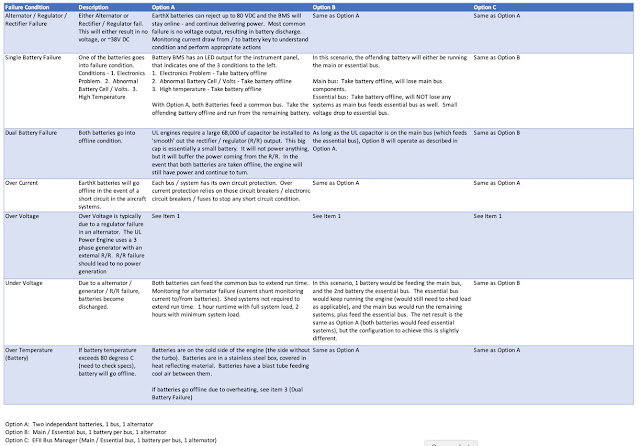
Below is a table of each option and how it should react in a specific failure condition.


So after months of research, discussions and pondering I am going with option A.
  • Simpler
  • No diode loss
  • All systems can be run of either battery, or both
  • Unlike standard lead acid or AGM batteries, the EarthX have their own monitoring - in theory you know what is happening
  • With the UL system (permanent magnet generator, not an alternator requiring voltage to excite the field coil) you can run without batteries (if capacitor installed on bus side).  In the event of complete battery failures, the engine will still run.
  • EarthX has built in over voltage rejection
  • Does require more manual intervention... pilot will have to monitor battery status, charge current / generator status, etc.  

Wednesday, 2 February 2022

Firewall - Part I

The partially completed fuselage kit I bought already had the firewall roughed out, along with all the brackets that tie the firewall to the fuselage.  Step 1 was to see how it fits...


Luckily, it fits very nicely :-)

Because I am not going with a 'standard' engine, I need to do a lot of stuff that is not in the book.  So I have been planning out where I am going to put everything.

Stuff to fit:

  • Batteries (including capacitors needed for UL install)
  • Voltage regulator (50A)
  • Gascolator
  • Fuel pumps / filters
  • Primary fuel feed / fuel injection return
  • Air / oil separator
  • Cabin heat box
  • Throttle, and cabin heat controls
  • Master relay(s) (do not need starter relay, as it is on the engine)
  • MAP sensor
  • Fuel pressure sensor (which is fitting to output of fine fuel filter, via banjo fitting)

In order to 'fit' everything, I had a local plexiglass shop make me a Plexiglas firewall.  They cut the outside profile of the firewall, and the slots that go around the nose gear mount.

I am not comfortable with the limited amount of hard points on the cage for attaching accessories.  So during this process, I am going to add a number of additional hard points.

My kit did not come with the material needed for the angle structure that goes on the firewall, so I ordered a bunch of 1.25 x 1.25 x 0.125 6061 T6 angle.

The Glasair documentation for anything firewall forward is very lacking... once I got over that and figured I am on my own, it started moving much quicker.  A lot of hunting and frustration was involved trying to figure out what to do.


Firewall Framework:  Glasair uses an aluminum angle structure (attached to hard points on the cage) to mount all accessories.  In a 'usual' Sportsman, this would include battery, oil cooler, engine transducers, firewall pass throughs for wiring, cabin heat box, etc.

Goal:  Have ZERO firewall penetrations that need to be removed.  Example:  Battery mounting - the goal will be to be able to remove the battery without having to remove a firewall penetration.  This will apply to everything.  Coils, fuel filters, regulator, etc.  Once the firewall and framework is mounted, nothing will need to be removed EVER.

With using a UL Power Engine, my needs are a bit different:
  1. (Electric) Fuel pumps (qty 2 - primary and backup, controlled by the ECU)
  2. Fuel filters (course and fine)
  3. Air / oil separator
  4. Gascolator
  5. Batteries (qty 2 - EarthX ETX900)
  6. Coil packs (qty 2)
  7. Master relays (qty 2 - one for each battery)
  8. Cabin heat box (stainless - Canadian requirement)
  9. Main fuel line (output from either pumps or header)
  10. Fuel injector return
Fuel Pumps / Fine Filters - Location (Note - also see Fuel System post for more details (add link)):  Option 1 will be to put the pumps on the forward tunnel inside the cockpit.  Option 2 is on the firewall.  Honestly, I don't like either option, but they have to go somewhere.  All of the hardware is ordered to adapt the standard UL pumps / filters to inline input and output rather than side entry.  With all this, it should fit in the tunnel.  If that doesn't work, then I will come back to putting all this stuff on the firewall.

I am pushing ahead with plan A - filters / pumps under the header, on top of the forward tunnel.  Something like this:


Tentative tank placement:


The firewall framework has been proceeding well.  Mounts made for coil packs, regulator, fuel filter, batteries, gascolator, etc.


Once the pump and filters are complete, then I can proceed to putting in the Plexiglas template and fitting the cabin heat box, cable passthroughs, air deflector, etc.  Hopefully then I can really start moving.

Plexi firewall in place.  Main fuel line drilled, as well as return.  Cabin heat airbox next.  Battery box clamped in place.


A lot of the above did not work out:
  • Battery box too wide and too low - hit engine mount (I finally had the brainwave I had better put it on and check for clearance issues...)
  • Gascolator not low enough.  Hit exit ramp that transitions between the bottom of the fuselage and firewall.
So I changed my mind on the battery box.  Decided to go stainless, and cover it in a reflective mat.  From reading on the forum, this seems to be a good option.  I will also put a 1" cooling flange on the front.

Redesigned the gascolator mount to be similar to the Glasair design (I am using the same Gascolator they use).


5 pieces to the battery box.  
  1. Floor the rivets from the bottom
  2. Back mount that will tie into the firewall structure on both sides.
  3. Front cover that wraps around to tie the back mount and floor together
  4. Strap that hold the batteries in.
To pull the batteries will require taking the box off, but it will only be 5 bolts (plus the wires) and the entire box comes out.

Firewall frame below removed for drilling / finishing.  The back is flush riveted so it won't interfere with the firewall.


Firewall frame all primed, relays temporarily mounted, gasolator fit checked, cabin heat box drilled.


Parts getting their grey coating to match the engine mount (and everything else)


Exit air ramp drilled.  The bottom is held in with captive fasteners on the bottom of the firewall stainless.  Screws will go through the fiberglass, air ramp, and then into the firewall structure.


Everything completed to date installed.  (New) plan is to finish all the cockpit / avionics wiring with the firewall out.  Real firewall will not be installed until after engine / engine mount has been test fit.

The firewall template has been out of the fuselage for a month or more while working on other things.  Its pretty much going to stay in this state until I have an engine.  Part II will cover the next phase of the firewall later in 2022.