I am at that point in the build where progress is frustrating because I have overcomplicated a lot of things. I decided to go with the Infinity Stick grips, and load up on functions on the grip itself. They are a really good grip it a lot of ways. Easy of installation and wiring is not one of them.
Well, thats not fair I guess. The installation is fairly straight forward... but you have to trim 1" off the stick to get it to fit under the panel, drill a big hole for a plastic bushing, and a slot for the wiring to pass through. But it nicely clamps onto the stick...
First things first... you need to set the fore / aft position of the stick. That means you need uphostery (which I ordered) first, then the sticks have to be drilled to the yoke. This is the part I have been avoiding because I was unsure how to tackle the issue. Since I have the fuel lines installed, you have to work around them.
So today after (what seems like months) of indecision (and talking to other builders), I tore into it. The holes have to be drilled through the yoke and stick, but I couldnt get my alignement jig on the yoke, so that means freehand drilling, which is prone to errors, plus you have to line up the sticks and I dont have the wings attached to center the ailerons. But, there is some adustment on the yoke, and turnbuckles. So I decided to just center the yoke with some wood blocks, center the sticks with a board (per the manual), and carry on bravely.
- 4 way hat switch
- Trigger switch
- Left and right thumb switches
- Middle thumb switch
- Pinky switch
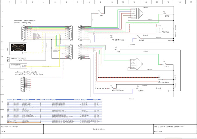
- 4 way hat switch: Pitch and roll trim
- Trigger switch - Push to talk
- Left and right thumb switches - Left(a): Autopilot disconnect / CWS. Right(b): Momentary toggle - forward, COM1 flip flop. Aft - COM2 flip flop.
- Middle thumb switch - Audio panel swap from COM1 to COM2 and vice verse.
- Pinky switch - Transponder IDENT
The Infinity Stick Grips are very nicely made, as assembled really well on top of the stick. After about 15 disassembles / reassemblies I am reasonable good at it. The issue is the wires... there are so many wires, and if they get caught in the channel for the stick, or against one of the bosses that the screws go through it wont go together. If any little thing is wrong, you are taking it all apart again. If you want a grip that you just mount on the top of a stick, this is not the one for you.
- Sorted through all the wires and found the ground (using an ohm meter), and separated them from the pack
- Tied all the ground together on the stick side using solder sleeves. There are 6 ground - so 3 into 1, then 2 into 1, then that wire went to the connector. Sleeves are hidden under head shrink.
- Checked functionality of every switch at all points in the process. Would really suck to get everything done and have a busted wire or bad ground.
- Connectorized the end using a d-sub 15.
- The connector will fit through, but without the shell, and it has to go through sideways. I left enough bare wire to get it through.
- IDENT: Goes to a PFD input on the AC Rear Connector
- COM 1 SWAP: Goes to the Dynon radio
- COM 2 SWAP: Will go to the yet to be purchased GARMIN NAV/COM
- Audio Panel SWAP: Goes directly to the Audio Panel.
To finally everything is done. Sticks are wired, connectors attached, everything tested good. Sticks are bolted in place.


No comments:
Post a Comment