Search This Blog

Tuesday, 16 November 2021

Vacuum Bagging - Test 1

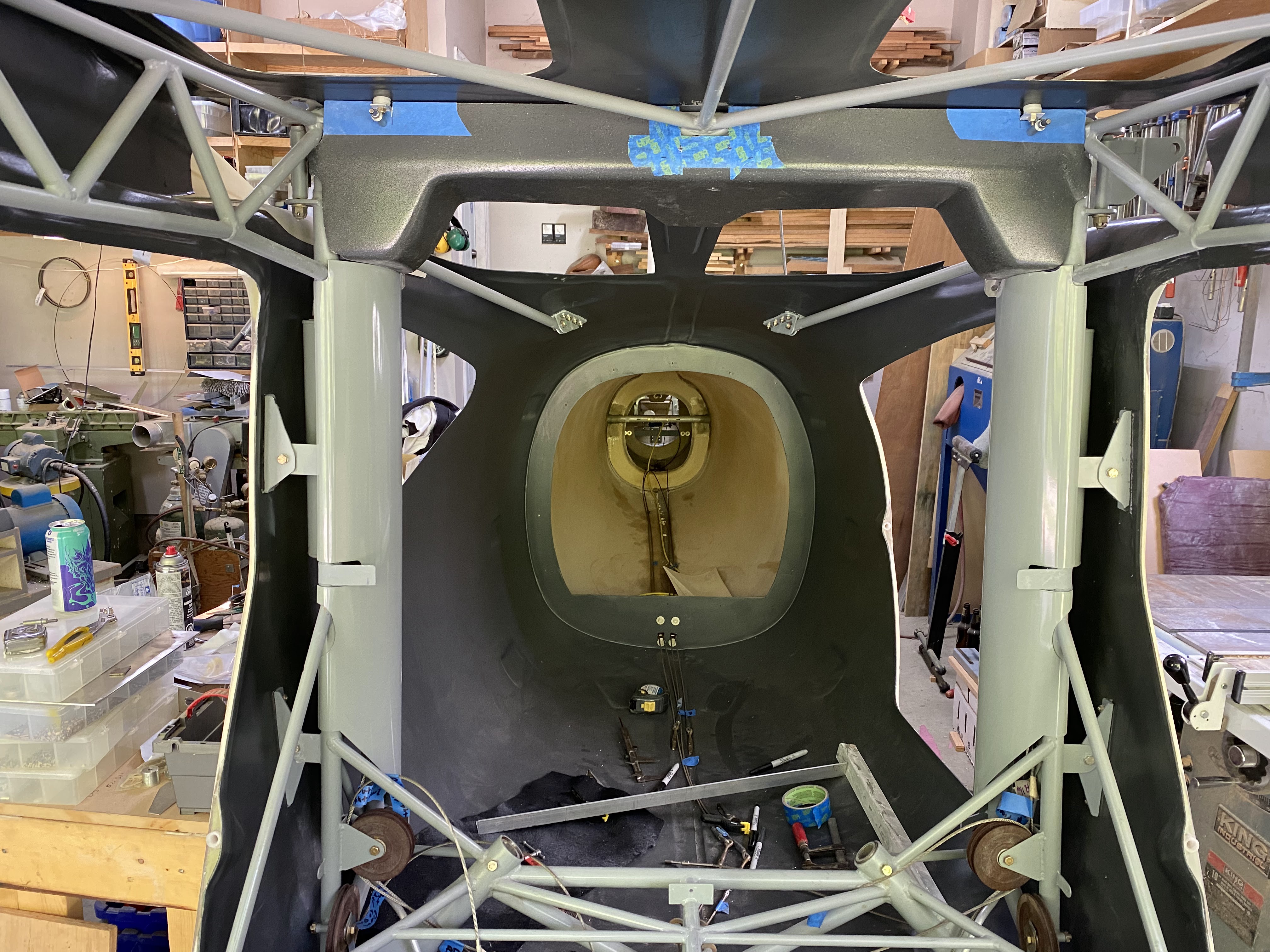
 I am building my own rear seats - but very similar to how Glasair does it.

In their design, the rear seat backs and bottoms are fiberglass / foam.

Having never done this before, I did some small test pieces, and laying it up is easy, its getting nice edges.

Talked to some fellow builders, and their solution is vacuum bagging.  A whole new skill to learn...

Here is a really good write up on vacuum bagging.

I purchased a vacuum bagging starter kit from Aircraft Spruce.

My first test piece was pretty small - about 4" x 6", 1/2" foam.

This is where I made my first mistake...  I lined my 'mold' with vacuum bag material, then a layer of breather material, then perforated film, then peel ply, then the fiberglass, then the foam.  Then more fiberglass, peel ply, perforated film, breather and bag material.  Essentially I had no mold.

Here is what the layup looked like before applying any vacuum.


After


A fellow builder loaned me a pump.  I bought the valve from Aircraft Spruce.

So I need to try again.  This time using only half the material.

Here is what came out of the first attempt.  Because I put peel ply down on top and bottom, it is stuck to itself along with the perforated film.


Definitely learned something from this...

2nd test

Slightly larger foam (6" x 8").  Used Aluminum tape on the mold, and waxed the area where the part will be laid down.


This time no bag material on the bottom.  Lay up (from bottom to top):

Aluminum tape

Wax (4 coats)

Peel ply

2 layers of glass

Foam

2 layers of glass

Peel ply

Perforated sheet

Bleeder

Bag


Finished part


I need to pull a bit more vacuum (and need a vacuum gauge), especially when trying to do the seat back that is roughly 3' by 3'.  More vacuum, more CFM.  Also, I have been told I am putting the bag on too tight.  It should be really loose.

But definitely going in the right direction.  


Tuesday, 24 August 2021

Gear leg fairings

The build manual gives to options for gear leg fairings.  Aluminum or Fibreglass.

For aluminum, the fairing is two pieces (an upper and lower due to the flex in the spring gear), and  wrapped over the leg, with a foam support structure to keep its shape, with a piano hinge on the aft side to hold it together.  The brake line runs down the aft side of the leg, and holes are drilled in the foam for it to run through.

For fiberglass, the brake line is bonded to the aft side of the leg, and then foam is glued over top and shaped into an airfoil shape (using the front side of the leg as the leading edge).  Fiberglass is layed up on top of the leg / foam, and then finished.

The kit comes with material for both options.

The below describes my 2nd attempt.  The first didn't work out quite right.  Close, but not close enough.

The trick here seems to be that you need the piano hinge to line up exactly the same on both sides.  I accomplished this by laying both pieces of aluminum on the edge of a bench (leftover from my wing jigs).  Clamped it down, and then laid the piano hinge down and drilled it in one piece over both sides - with the intent to cut it later.


I predrilled all the holes on the piano hinge, then clamped it down to the table as well.


Once I had drilled everything I could, I drilled some extra deep holes into the wood and clecoed to the bench.  Then I could remove the clamps and drill the last couple holes


To put the bend in the skin, the manual recommends wrapping it around a broomstick.  On my first attempt, I wrapped it around an axle, and it worked OK.  However, the RV guys use a trick to bend their ailerons and flaps.... Make a channel slightly wider than your bending form (AKA broomstick), and then lay your material down, and force the broomstick into the channel.


I raised my tabletop up off the bench to get clearance.  I had some scrap MDF strips laying around (about 3" wide) and clamped them to the top.  Again, needs to be a hair wider than your broomstick.  Mark the centrelines on your piece, line it up, and push the broomstick down.


I used clamps to force the broomstick down.  In the past I had glued / screwed this contraption together, and then you can just straddle the piece and step on the broomstick.  Clamps work once you get them aligned.

This also worked out nice for taping the trailing edge.  Leave the piece in the form, apply tape (I used Gorilla brand duct tape) to one side, then aligned and pinch the trailing edges together and push the tape over the top.  Worked out real nice.


And voila!  Bent and taped...


The above is both pieces (upper and lower).  I fed the lower down through the top to check the overlap.  I need to take about 3/32 off the lower piece before drilling the other half of the piano hinge.


You can see my first attempt the lower part of the gear leg.  Also, you can see the mounts I have made...

After trimming the lower leg to fit inside the upper, I marked and drilled the 2nd half of the piano hinge using the same method - but with the 2nd half of the piano hinge clecoed in place.


At this point, the piano hinge is still one piece.  I figure this is the best way to make sure it lines up.  Need a small gap between the two halves so there is room for it to wrap around.


Two halves joined with the piano hinge.  The alignment is pretty good.  The lower half needs a small trim on the trailing edge for them to line up perfectly.  The nice thing is its super easy to see now.  Will take it to the sheer in a couple days.


Overlap detail.  No real way around this.

Left hand gear leg fairing installed.


I am fairly happy with this one.

Now I just have to replicate it one more time...


Sunday, 15 August 2021

Crossover Cable Cover / Vertical Pillar Covers / 4 Point Harness Bar

 Back in January 2021 I purchased the upper cable cover from Glasair.  Well, finally getting around to installing it.

On newer Sportsman cages, there are 4 tabs along the front that it mounts to.  I don't have those.

My plan is to pickup to outer fuselage mounts on the front, then make a bracket that can be hose clamped to the cage tube in the middle.  The rear will be 4 composite L brackets bonded to the fuselage shell.  This is how Glasair does it (well, the rear at least).

So far the cover has required a bit of tweaking.  The cutouts for the tabs shown in the picture were not present, and the outer contour did not match my cage tubes.  But was still a lot better than building the whole thing!  Also, I don't think the cover will fit with the vertical cable covers.... but will find out shortly.


The crossover cable cover definitely interferes with the vertical covers.  So I marked it out using templates, and cut it back using a dremel and drum sander.  The starboard side cover was interfering with the diagonal tube off the horizontal bar under the seat, so it was dealt with as well.

Then there is the seat belt harness bar.  There appears to be no provisions for the harness bar clamps in the vertical pillar cover.  So these corners were 'relieved' to make it all fit.


All the cuts need to be cleaned up, and I am going to wrap the vertical pillar covers.  Depending on the extent of refinishing for the crossover cover I will either leave it or repaint the same as everything else.  Undecided at this point.

My main point of 'pissed-off-ness'.  The vertical covers were finished.  The crossover cable was finished.  The harness bar was designed and published AFTER both the vertical and crossover covers were purchased.  WHY THE HELL DO THEY NOT FIT.

My cage had the 3 point bracket on the vertical pillar, and the cover did not have a clearance for that.  Well, I get it.  Due to its age, that makes sense.  But it doesn't have the provision for the harness bar either.  So what gives?  One of the two options should have a provision to mount it.  This is EXACTLY why I get so frustrated with Glasair.  Someone just IS NOT THINKING.

Rant off.


First composite L bracket bonded for the crossover cable cover.

To make the L bracket, took 2 pieces of 3" wide MDF and screwed them together.  Then applied liberal amounts of packing tape.  6 layers of cloth, with peel ply on top.  Cure overnight, pop out of mold, run through table saw to straighten the edge and then chop into 1.25" sections.

Covered the area with aluminum tape, leaving the area to be sanded exposed.  Sand, vacuum, etc.  Mixed up a batch of thick resin / cabosil / milled fibres.  Was thick enough to hold itself in place while bonding.

3 more to go!  Should be easy now that I have a process...


All in.  Just needs to dry.

My brother in law gave me a big roll of aluminum tape, and I used it to mask off the sections for sanding and bonding.  Once bonded, just pull it off.  Seems to work well.


Pilot holes drilled through the crossover cable cover and aft tabs.  Now onto fasteners.  Using #8 captive fasters and not self tapping screws.

Monday, 5 July 2021

Batteries, Battery Box, and the start of wiring...

Decisions to be made (well, have already been made - but here is the logic)...

Batteries, and battery capacity:  I like lithium batteries - specifically EarthX.  Lots of views on this subject.  Regardless, that is my choice.  Next decision is size and capacity.

Size:  Need to be able to run everything for 1 hour minimum on battery power alone.  Panel will draw 10 amps, engine will draw 12 (including pumps).  Going with qty 2 EarthX ETX900's, which are 16.4Ah batteries.

Charging:  Already decided on batteries, now what keeps them charged.  The UL520T comes with a 50A alternator.  There is an option for a 2nd alternator, but when you do that you now need to control the charge direction - IE what alternator charges what battery.  2 alterators is more weight, then you add diodes that generate heat, add complexity, and slightly drop voltage.  All things considered, going with 1 alternator and 2 batteries seems to be the most prudent.  Best balance of benefits vs complexity.

2 batteries means 2 master solenoids.  No big deal... just need to find space.

Battery mounting:  My goal is to make this airplane serviceable... as easily serviceable as possible.  Changing batteries should be an easy process.  With that in mind, the battery tray is going to bolt to the aluminum angle framework.  No firewall penetration to remove the battery tray / batteries.


This battery frame is going to have an aluminum box around it with a blast tube.  The top and bottom will be open.  The shroud will have reflective stick on material.  At least, that is the plan...

Battery frame all drilled and clecoed.  Adding some .030 side pieces for a bit more rigidity.  Will drill some lightening / cooling holes in these as well.

Lot of drilling..... 


Everything primed and alodyned.


Initial test fit.  I am not going to commit to a location yet.  I need to see where the intercooler is going to be.  It is somewhere in this area.


Test fit with batteries.  Just need to make the hold down strap.


Unfortunately this design is not going to work.  After test fitting with the engine mount, it hits.  Didn't seem to matter where I moved it, it wasn't going to work - mainly due to its width.

Version 2 is stainless and narrower.


Will still be mounted on its sides in a cradle.  Hold down strap to keep the batteries in.  Changing the batteries will mean removing the whole battery box due to the engine mount, but its only 5 bolts to get it out.


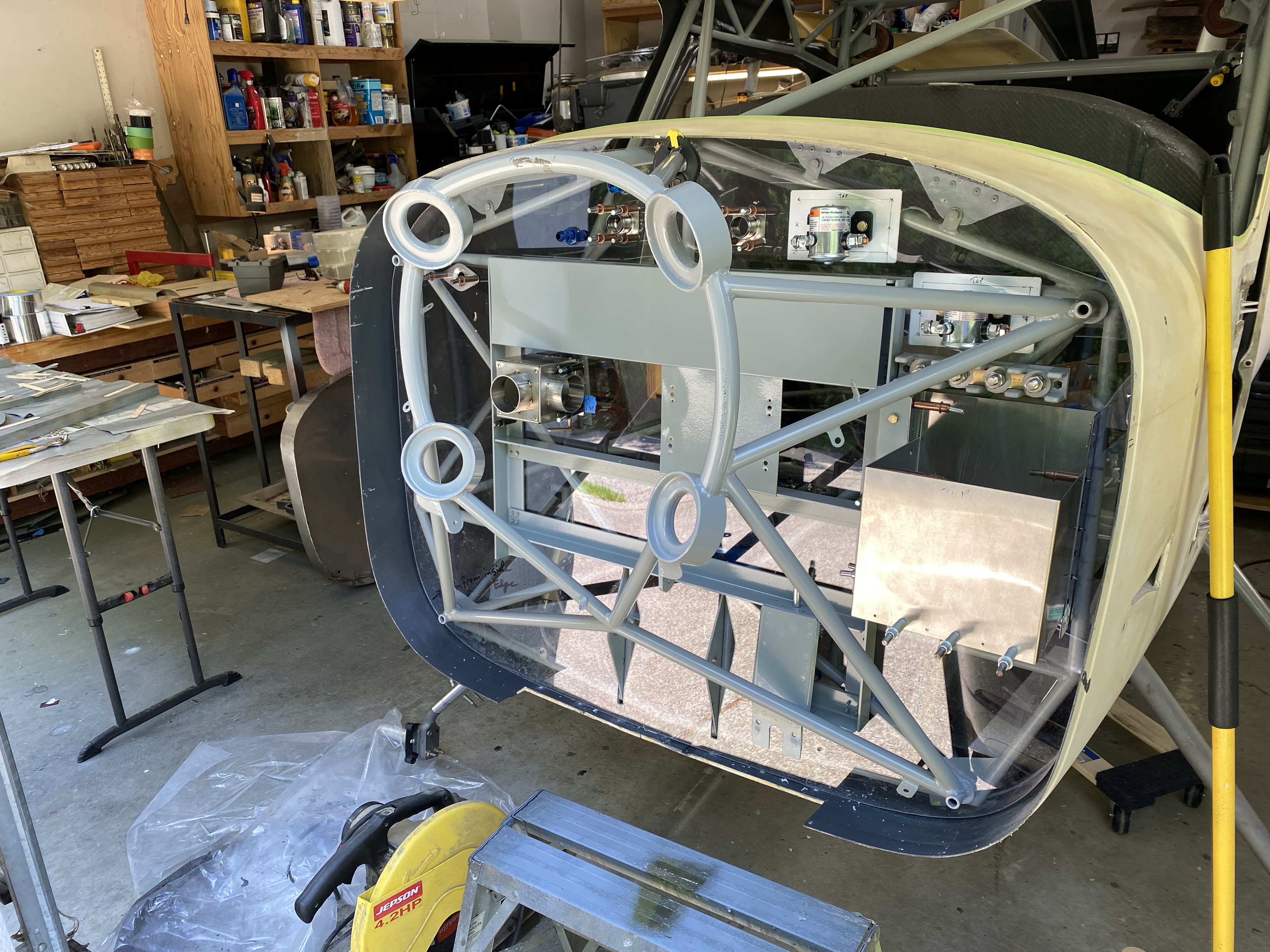
Installed on the firewall - test fit...

Moved the ground bus bar up higher.... had no access to tighten the ground screws down.  I figure that the best way to figure out if this is a workable solution is to just wire it.


Needs tidying up, but I am not unhappy with the results.  Everything is accessible and safe.  I am not going to go much beyond this until the firewall is in for good.


Wednesday, 23 June 2021

"Mark" Reservation (aka callsign)

 Today I received the confirmation that my project "mark" has been reserved by Transport Canada!


Next step is registration, which will hopefully happen next year.

Friday, 7 May 2021

Rudder Pedals and Brakes

 I am lucky enough to have the cast rudder pedals with my kit.  As part of the repaint, I removed everything and either cleaned, painted or anodized the parts.

Rudder pedals after anodizing


They didn't come out really black, but kind of a dark grey.  I think they will look good.

Refurbished pedals installed.


Setting the pedal angle.  I made a block that fits between the top of the torque tube and cage that sets the distance.


All of the nylon brake lines have been replaced with teflon / stainless steel braid (Aeroquip).  Also, a Matco parking brake was added under the forward tunnel.

I put the reservoir close to the stock location, but mounted it with an Adel clamp.  I don't see any reason to mount this to the firewall.  Also, I used teflon lines all the way up to the reservoir (the 2004 manual says use Nylon... the TWTT instructions use teflon / stainless for everything but the reservoir).

All brakes lines have been run, except to the callipers (up to the park brake).


All of the lines still need to be spiral wrapped / tie wrapped.  But everything is connected.  Will drill the holes down to the callipers once the gear legs have been powder coated and gear leg fairings completed.

January 2022 update.

Finally got around to spiral wrapping the brake lines, and attaching the hose coming down from the reservoir.


Probably overkill, but in that area I have my park brake cable, vent line, and brake fluid reservoir.  I really don't want anything to touch / rub.


I probably spiral wrapped more then I needed to as well, but oh well.  Its light stuff.


Tuesday, 13 April 2021

Extended Heavy Duty Main Gear

 The gear truss upgrade done earlier in 2021 was in order to be able to handle larger main wheels - specifically 31" Alaska Bushwheels.


Ordered the legs from Langair in January, and the arrived early April.  I had a shoulder added to the leg to be able to add a step at a later date.


Drilled a small hole from the top of the gear socket down through the fibreglass (with a very long bit), then opened it up with a unibit, then a small drum sander on the end of a drill.

There was some corrosion in the sockets, and some overspray.  So again, with a drum sander I very carefully cleaned everything up, and then cleaned out the socket with some WD40, a rag, and a long screwdriver to push it through a few times.

They are REALLY tight.  Had to pound them in the last inch with a rubber mallet.  Hopefully they come out again :-)

I bought two 100" lengths of 1.5 x 1.5 x 0.25" angle for levelling the legs and setting the toe.

Next step is alignment.

There have been a huge number of posts on this subject.... but here are the goals:

  1. Level the legs.  Each leg needs to be within 1/8" of the top of the socket, and the gear legs need to be level from side to side.
  2. Set the toe.  For tail drawers, we want somewhere between 0.5 and 1 degree toe OUT.
With the fuselage level (by adjusting the tire pressure), I inserted the legs.


The manual states to grease them, which I did.  They move steadily with the liberal application of a heavy rubber mallet.

My original plan was to clamp the aluminum angle to the outside of the axles.  Yeah, bad idea.  Using the forum, turn the axle around (temporarily) and bolt them to the INSIDE.  Trimmed the aluminum angle down, and presto


After lots of frustrations with clamps and blocks of wood, I decided to make a platform that the aluminum angle sits on.  using various shapes and sizes of wood I had laying around, I lifted the angle into position against the axle.

I achieved the initial goal of having the fuselage level, gear level, and 0 degrees toe.  However, I am slightly out on the pilot side gear truss.  It needs to be within 0.125 of the top of the socket, and currently it is .142.  I need to move BOTH sides up slightly.  8 whacks of the mallet on both sides brought the left side into .121, and the right side is slightly proud.  Level shows that the gear legs are 0.05 degrees.  I am good with that.

(NOTE:  The below procedure did not work.  Follow up on the end about what to do to fix it.)

Inserted an .030 shim on the INSIDE of my turned around gear leg on both sides.  Bit of mallet work, check level on everything again, and that should give me a little bit less than 0.5 degree of toe out.  I am gong to work the math tomorrow to validate, plus I have emailed the forum for double check guidance.

I haven't done much trig in years, but with the help of google I figured it out.

Radius of the tire = 15.5" (31" bush wheels)
Axle length = 4"
At 0 degrees toe (which is 90 degrees for the triangle formula), the hypotenuse is 16.008".  Adding shims to the hypotenuse, then solving for the to angle.

0.030 shim = 0.43 degrees / 0.23" of toe (per wheel - 0.46 total), 
0.040 shim = 0.6 degrees / 0.32" of toe
0.067 shim = 1 degree / 0.54" of toe

I drilled everything, and pushed it outside, put on the tires and measured the toe.  Definitely toed IN (not desired).


Rough toe measurements with tired on (I am going to repeat this again with angle on the ground.

Front:  102"
Back:  104"

Toe calculator (inches to degrees):  https://robrobinette.com/ConvertToeInchesToDegrees.htm

According to this, I am about 3 degrees toe IN, which is bad.

With everything apart and back in the garage and levelled, the legs are again slightly toe OUT.

The only good news is the legs are exactly level.

I am going to stop working on the gear at this point.  I think once the wings, engine, panel, interior, etc are all installed the toe measurements will again change.  So there is no point fighting this now, just to fight it again later.  My gut says that once there is weight on the gear, the toe will go out, but I don't know how much.  Shims are available to change the toe angle, but I don't know which ones to buy.

Moving on to something else...