Search This Blog

Thursday, 11 August 2022

Engine Installation - Part I

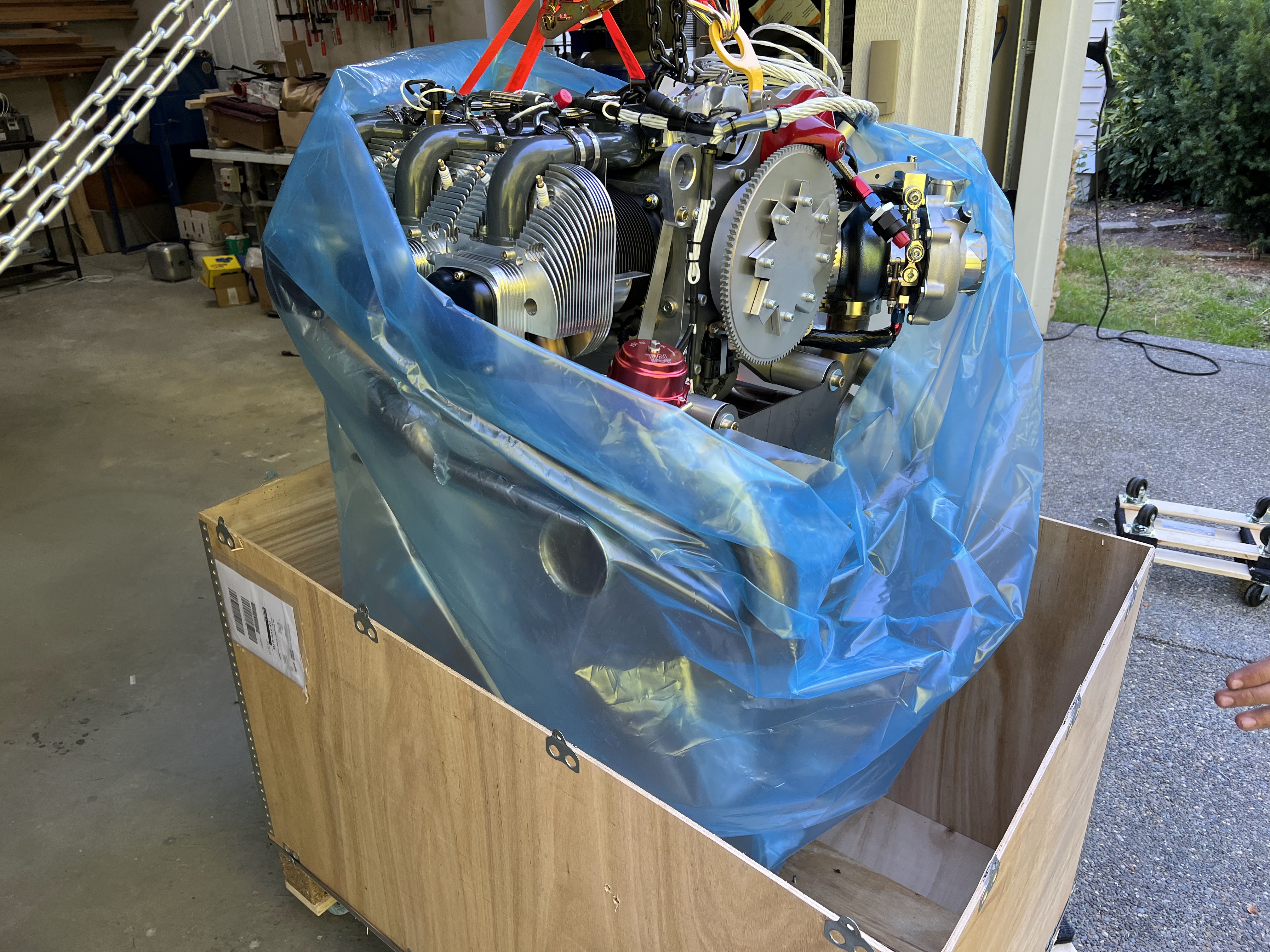
 Very cool evening.  My son and I installed the UL520T on the airframe.  Took around an hour between freeing the engine from the crate, lifting it, and assembling all the mount hardware.

No major issues.  The only thing that needs some follow up is an oil line either to or from the sump is too close to the engine mount washer.  Will follow up with UL and find a solution.

The engine wiring looks pretty straight forward.  2 large cannon plug connectors to the ECU, and various fanouts for power, ground, coils, regulator, etc.  That will be a project for next week.


Next challenge is fitting and extending the cowl.  Hope to start on that next week.  Waiting for the prop.  Has been ready to ship since late June, and paid for since mid-July.  But I know the required spacing, so I should be able to start.


Tuesday, 9 August 2022

Instrument Panel - Part III (Wiring)

Now the wiring begins.... I both love and dread this part.  Love it because it makes things work, and dread because compromises will need to be made.

Step 1:  Electrical bus(ses).

Target is 3:

1. ACM - which includes avionics, lights, pitot heat, etc.  Everything that the ACM powers, which is everything but engine.

2.  Engine bus.  Stand alone bus for the engine, using breakers.

3.  Everything else bus.  This will be fuses, and for things that dont really matter - like seat heaters.  This will be the last priority.

The output of the two batteries goes to a central point, which is the current shunt.  This shunt will measure the total input / output to the batteries and will be inclusive of everything.  From the shunt, power goes 3 ways - to the ACM, Engine Bus, and to a fuse panel.

Fuel Pumps

The UL Power ECU has the provision to 'control' the fuel pump (or pumps) via a relay.  The ECU drives the coil on the relay (Fuel Pump Control Relay - FPCR), so it can turn the pumps on or off.  This is useful when on the ground working on things.  The system will pressurize, then the pumps shut off.

However, what if the relay fails?  So my fuel pumps switches have an 'auto' position (which goes through the relays) and 'force', which does not go through the FPCR.  Overkill?  maybe.

Everything else engine needs to wait until it arrives - hopefully in late May.

From a wiring perspective... 2 power feeds from each of the pump breakers.  1 feed goes directly to the switch, one goes to the FPCR.  The center position of the switches goes to the pumps.  The pump wiring is on a connector as the whole fuel pump tray is removable (kinda - have to take the header tank out first).


Header tank sensors.

Well this has been fun.  The sensors I bought from Radiant are cool, and I tested them very thoroughly with water to ensure they do what they should do.  But their connectors are, lets say, interesting.

The sensor is connected with a USB cable.  The head unit (of which I have 2) has the power connections.  Plus the cable lengths were way too long.  So I shorted everything up and put them both on one connector.


They are temporarily wired to power off a breaker to verify the wiring and connector.  Debating whether to power them from the ACM or a breaker or fuse.  Probably the ACM long term.


They flash red when liquid is not present.  Obviously the tank is empty, which is a good sign.

Radient recommends siliconing the LED's into the holes.  Not sure if I am going to do that, or make a mount.


ACM and Pre-Built Harnesses

I love the ACM.  I love the harnesses.  I have to figure out how to tame them.

To start, I plugged everything in.  No wires are tied in anywhere.  Just wanted to get the lay of the land (so to speak).  Holy crap, its a lot of wires and I am nowhere near done yet.

Dont judge me based on these pics.  Please.


The plan is to figure out where everything will go, then take it all apart and finish the trays and brackets, then reassemble for good. But I have to build the aircraft front, rear, and wing harnesses.  Everything is ordered to do that.

Main Power Distribution

OK - this is a mess.  But you have to start somewhere.  Again, the purpose was to figure out what goes where.


Two EarthX ETX900 batteries, two master relays with flyback diodes.  Each battery can be switched in or out.  This is all pseudo temporary, but it works.

The output of the two relays is bridged together, and the starter will come off here.  From the bridge point, goes to the main shunt with 6 gauge wire.  From there, goes to the ACM and engine bus.  The battery, aircraft frame, and engine all tied to a single firewall ground point.  Also a 10 gauge wire to the avionics bay ground bus.  This may need to increase to 8 gauge.

Engine Bus

As the ACM shies away from anything 'engine' related, I decided to have breakers for everything engine and fuel related.


10 gauge wire coming from the main current shunt on the hot side of the firewall.  It passes through a Hall effect sensor, so I will know (in theory) the current draw of everything engine / fuel related (but I won't know what is drawing what - just the total).


The Hall effect sensor is mount under the starboard avionics tray.  This may have to move simply for serviceability.  It will be very difficult to change - if not impossible.  On 2nd thought, if the MFD is removed there is a clear shot to it, but all of the wiring is not yet installed so that may change.  Time will tell.

Harnesses to build

- Aircraft front:  Comprises of prop controller, taxi lights (which will go to the wings - but that is a different story), cabin lights, panel fans, belly strobe, elevator trim.

- Autopilot servos:  These are pre-built from Advanced, need to be terminated on servo end.

- Sticks and flaps:  PTT, AP disconnect, IDENT, flip flops, Audio Panel switch, flap position potentiometer

- Wings (aka Aircraft Rear):  Pitot heat, landing / taxi lights, nav / strobes, fuel transfer pumps

- Engine sensors:  EGT, CHT, Fuel Pressure, CANBUS (to ECU, which has a large number of sensors), fuel tank sensors, etc.

The panel has taken a bit of a back seat due to waiting for a new panel from Glasair.  Should be here August 9th, then I have to recut it all over again.


Autopilot / Servo Wiring and Avionics Trays

 As part of my avionics package from Advanced, I purchased their pitch and roll servos.  All the servos come from the same manufacturer... also purchased the servo mounting tray from Glasair.

All of the brackets have been fit, fasteners drilled, and I added a few lightening holes in the tray itself.  While I was at it, I finished the left and right avionics trays that mount to the cage.  Lots of drilling and fitting nutplates.

All these were put through aluimiprep, alodyne, primed and painted.  The paint is PPG, and matches the grey of the cage.


Remote radio unit repositioned slightly due to cable length.

Everything dry fit.


Installed and wired.  I was SOOO careful to not mix up the wiring for the pitch and roll servos, and guess what - I cut them the wrong lengths.  So I de-pinned the connector and switched everything around.  


Left and right avionics trays are finished and nut plates installed.


The top picture is the left side tray (the IBBS is mounted under the tray). The next two pics are the right side tray.  I have not mounted the audio panel or Hall effect sensor yet... waiting for hardware.

I am going to need to raise the EMS and Audio Panel to clear nut plates underneath (they overlap each other slightly).

Handful of things to do before they are mounted - and actually will not be fully mounted until the firewall comes out.  2 holes need to be drilled in the forward tabs for the trays.

Next is the big tray that will hold the ACM, Skyview Network Hub, ECU, Boost Controller, Aux Box, and ADHRS.  I very quickly put it together to see if it was going to do what I wanted, with stuff I had in the shop.


Now that I think this is going to work, have gone back and finished drilling it, and making a few modifications, plus adding lightening holes.  Oh, and drilling for fasteners.... ugh.


After finishing, ready to mount.


Installed with most components present.


Lots of wiring still to do, but progress is definitely being made.


Engine and Engine Mount

The engine (UL 520T) has shipped from the factory.  Ordered March 20, was ready to ship in late June.  Also, prop is ready to ship as well once they receive the funds.  Big steps coming.

Engine mount received from Francois C.


Engine received on July 15!


Going to be a month or so before the engine is mounted.  Targeting mid August.

Originally I had the pre-filters and pumps on the cage, under the header in the cockpit.  The new UL pre filters are much larger, and reusable.  I had to relocate to the firewall.  Also, the coils and regulator are now mounted.


This new arrangement makes header tank situation much easier to deal with.  Just a single 1/2" line from the output of the header tank to the firewall.  The firewall bulkhead fitting had to be increased from -6 to -8 (3/8 to 1/2")


The above is the required UL power capacitor.  According to UL, this allows you to shut off the battery during flight.  Not sure I would want to do that.

Strakes

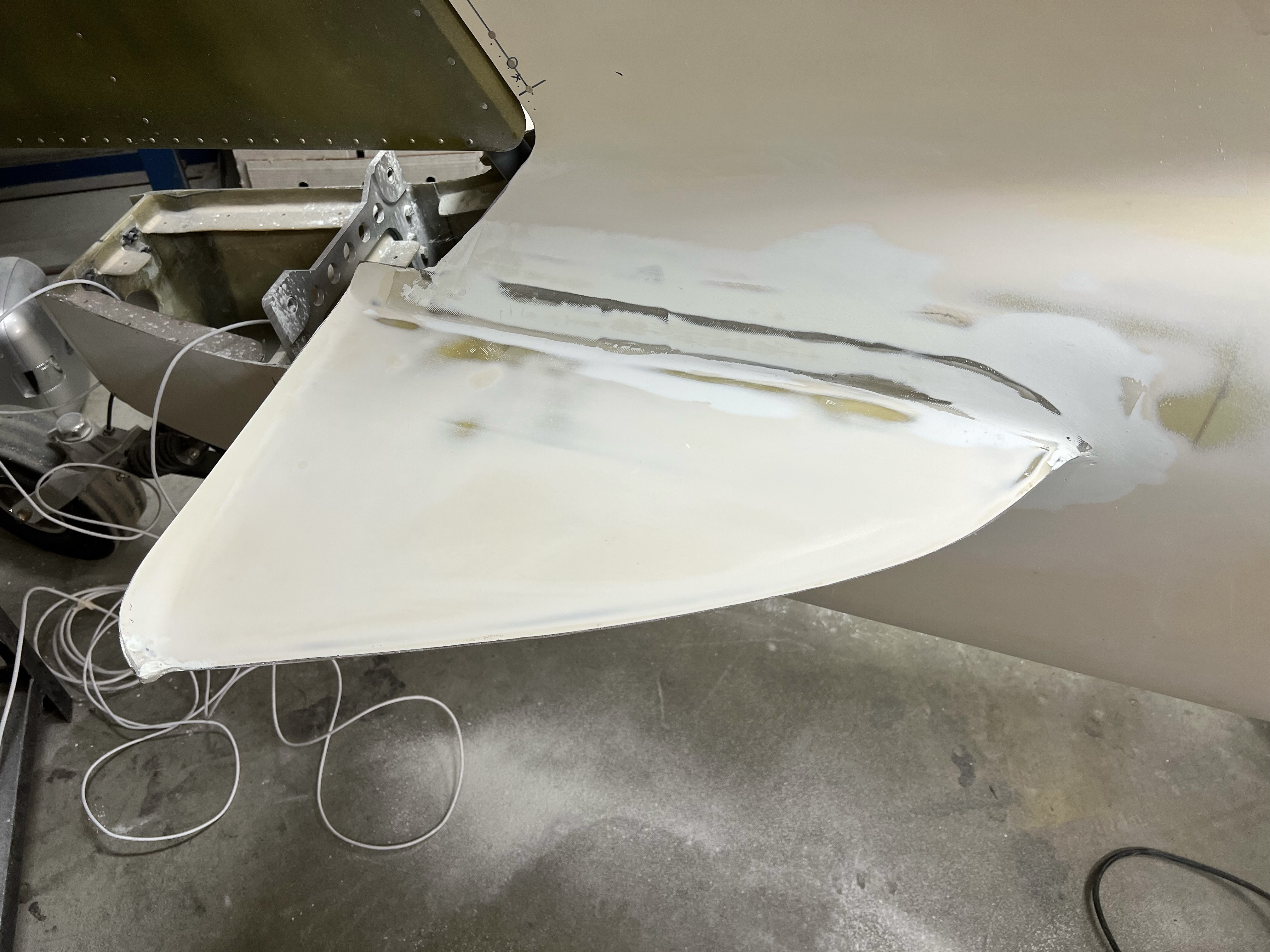
 The first builder that started the fuselage bonded the strakes on.  This involves bonding in the foam ribs, and the two halves of the strake, and then fitting the assembly to the fuselage.  My engine is inbound, so my goal is to finish up all of the messy / dusty stuff before it arrives if possible.

This picture is the strakes as they were when I bought the fuselage, but with a quick sand.


First layer of filler.  Just trying to fill the low spots.


Second later of filler.  Working on build the profile, plus the transition.


Third layer:  High build primer.  This way I can see what I have missed and refine the transition and any low spots.

Primer sanded...

2nd layer of high build


Multiple small imperfections still exist.  Putting this aside for now.  90 to 95% done.


Monday, 16 May 2022

TailBeaconX

The uAvionix TailBeaconX is a very cool little beast.  Has its own GPS, mode S transponder, and ADSB in and out.  Oh, and a light...

AND, its supported by the AFS-5600, so you can drive it from the PFD and MFD.

The wiring is pretty simple.  Power, ground, RS232 TX and RX.

In my case, I am mounting it inside the fuselage about 12" behind bulkhead A.  The mounting bracket and unit weigh less than half a pound.  The wiring weighs the same, if not more.

Other than the fact that when I wired it I mixed up the TX and RX lines, it worked right away.

The TailBeaconX is configured through wifi.  There is an app for your smartphone, and you set everything up through that.

Using the app should be straightforward, and once you follow this process it does work.  Took me awhile to find it.

Advanced already setup the PFD and MFD to talk to it, you just have to initialize it through the Set->Admin>Transponder menu.

Unfortunately our house has foil in the roof, and is stucco.  Basically a faraday cage.  No traffic being shown, but one day I will push it outside and see what I can see.


So after some fussing about, I realized that the TailBeaconX only does ADSB-OUT - not IN.  That is fine, since I have a separate dual band ADSB receiver from Dynon.

Mounting... simple fiberglass bracket bonded just behind bulkhead A.


The transponder and mounting bracket weigh 5.25 oz.

Installed, wired and configured...


Still need to secure the wires, but the mounts are already in place (and epoxied in).


Dont know if it is actually working or not, but it seems to be.

One really important note:  Some of the configuration needs to happen on the tail beacon.  This is done through the build in wifi access point in the TBx itself.  You can only configure it when the transponder is in standby - which makes sense.  I was trying to verify the configuration and had the transponder 'ON" on the EFIS.... uAvionix support figured that out really fast.

Super cool technology.


Miscellaneous 'STUFF'

Have been diligently working away on a number of items.  So this is a real grab bag of things that are underway.

Headset Jacks

In my package from Advanced, I received a harness for all of the audio jacks.  4 phones, 4 mics, plus a hardwired music input.  I did tell them how long to make it :-).

I was debating on where to put the jacks.  There were a number of options:

  1. Overhead cable cover (right behind the pilot / copilot's heads)
  2. Overhead console (from Fibertech composites).  I have my tailwheel lock and light installed in here.  Could use the sides, but they are not terribly strong.
So after a bunch of debate I decided to put them where Glasair does.... in the aft center of the cable cover.  Most just drill holes and seat the jacks.  I decided to get a nice little engraved and painted plate to mount there.

I had been looking for an excuse to try Front Panel Express. They have their own design software, and give you a price.  Below is my final design using their software.


For small stuff, you can print to scale.  Below is a previous version of the design that I printed and checked.


I ordered the plate on a Friday afternoon.  It shipped the next Tuesday (I ordered 5 business day turn around, but they shipped it in 2).  Delivered Wednesday.

Cost:  $88 USD, $96 with Tax.  Shipping included.

Once received I cut the hole in the cover.  The panel will fit through the hole sideways if needed for future removal.

To secure the wiring, I took some standard plastic tie wrap mounts and ground off the sticky backing.  Took as much off as I could with a knife first, then use the belt sander on the rest.  Then I epoxied the mounts to the inside of the cover after sanding and cleaning the target area.

Then it was just tie wrapping the harness in place (taking note to ensure that the cables will not rub).


The cover easily slipped in place.

The harness is then tie wrapped to the vertical risers on the aft side (again, keeping them away from the cables).


Previously I had cut, fit and finished the overhead console that houses the cabin light and tailwheel lock.  Need to wire it...  

The ACM has an output for cabin lighting, that can either be 'always on' or switched.  I am going for the always on option.  2x22 gauge wires run along the upper beam and tie wrapped.  There is a 2 position connector inside the overhead console for easy disconnect if / when needed.  Have not terminated on the ACM yet, but that will be soon enough.

Temporarily wired to a 12 power supply to check connections.


Lastly, I finally decided to ditch the trike gear legs (ditch = remove from fuselage).  I had been leaving them on as it make removing the main gear legs super easy.  All the final hardware is installed on the main gear legs, so it was time.


Back to wiring... going to work on the rear first.  Belly strobe, elevator trim, etc.  Ordered all the RG400 I am going to need, so will get that soon hopefully.