Search This Blog

Monday, 20 May 2024

Intercooler - Part II


Intercooler, plenum and ducting moving along slowly.

Spend the day yesterday getting the brackets, plenum, etc all ready for paint.  Finishing up all the drilling, deburring, fastener prep, 3" holes for the ducts, acid etch, alodyne, etc.  I thought it would take an hour... 4 hours later...  Everything is primed and paint is going on now.

I decided to use epoxy primer this time rather than zinc chromate.  What a difference... the primer sticks better, and the paint goes on REALLY well on top.


Next is riveting... 


Intercooler bracket all riveted with nutplates installed.


Plenum and flanges riveted.  Test fit on the bottom bracket.  All good.


Test fit on the intercooler.  Snaps right into place.  One tiny interference issue on the intake tube.  Fixed.


Bonded in place using leftover firewall silicon goop.  I also put a small bead of the goop on the seam on the inside of the plenum.  It shouldnt leak much, but every little bit helps.

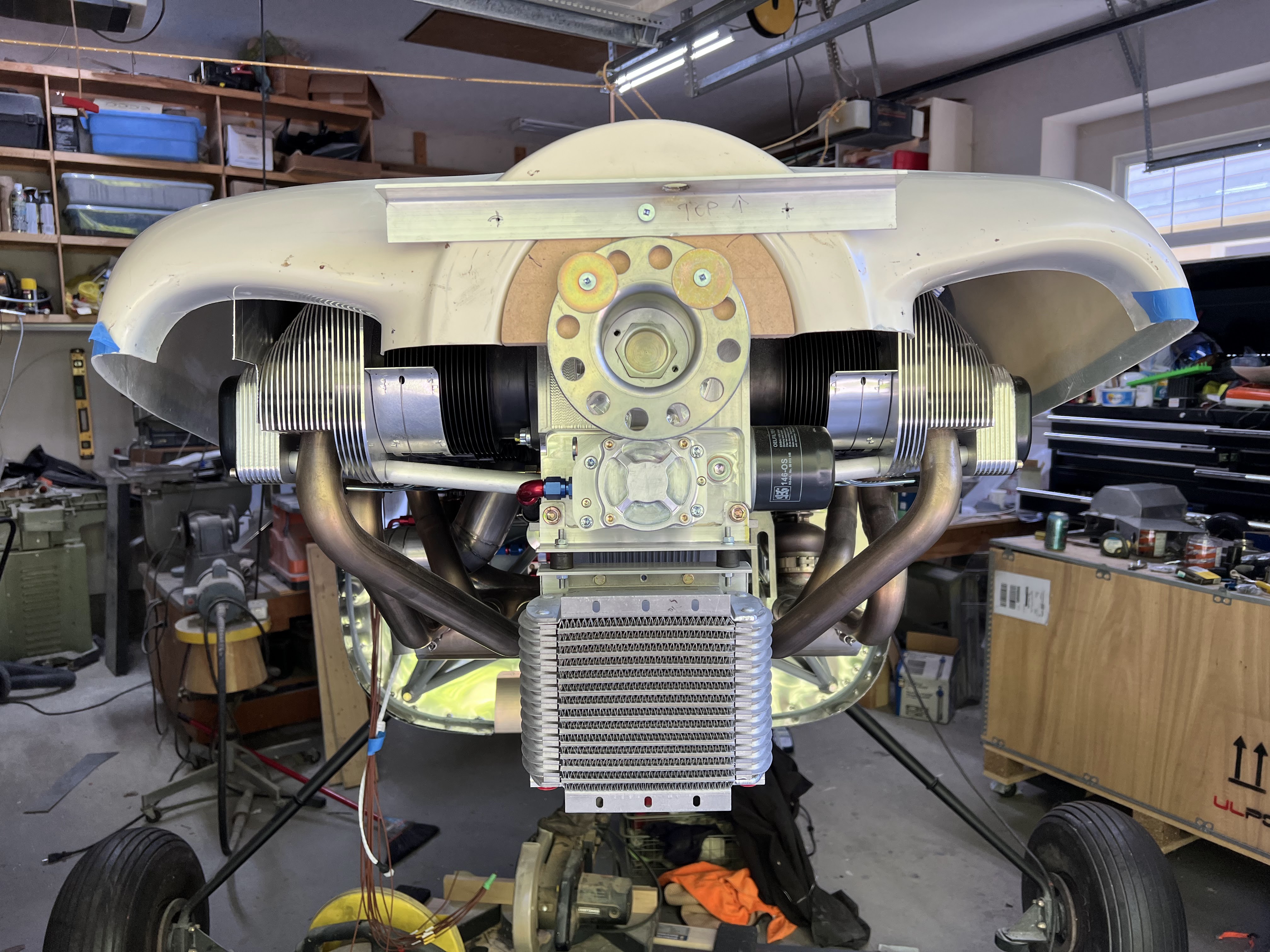
Installed...


Its a bit of a puzzle to install.  The intercooler (minus the plenum) fits right in no problem.  But to get the plenum in, the intercooler needs the bottom mounts free, and the top mounts loose.

So onto the intercooler inlets.  My plan is to use the outside of the cylinder inlet D and feed it to the intercooler.  My first attempt at this was MDF and dry wall mud - dont do that.  It worked, but took forever to dry and cracked a lot.  I finally finished it weeks later.

For the other side, I used foam - 1/2" foam to be exact, and cut / laminated it.  Here are the two of them side by side.  The white one is the MDF / drywall mold (starboard side), and the foam one is in its early stages (port side).


I am going to lay it up in three separate pieces, and then bond them together - top, rear and bottom.  I know this is not ideal, but I dont want to destroy the mold.

First piece laminated up.
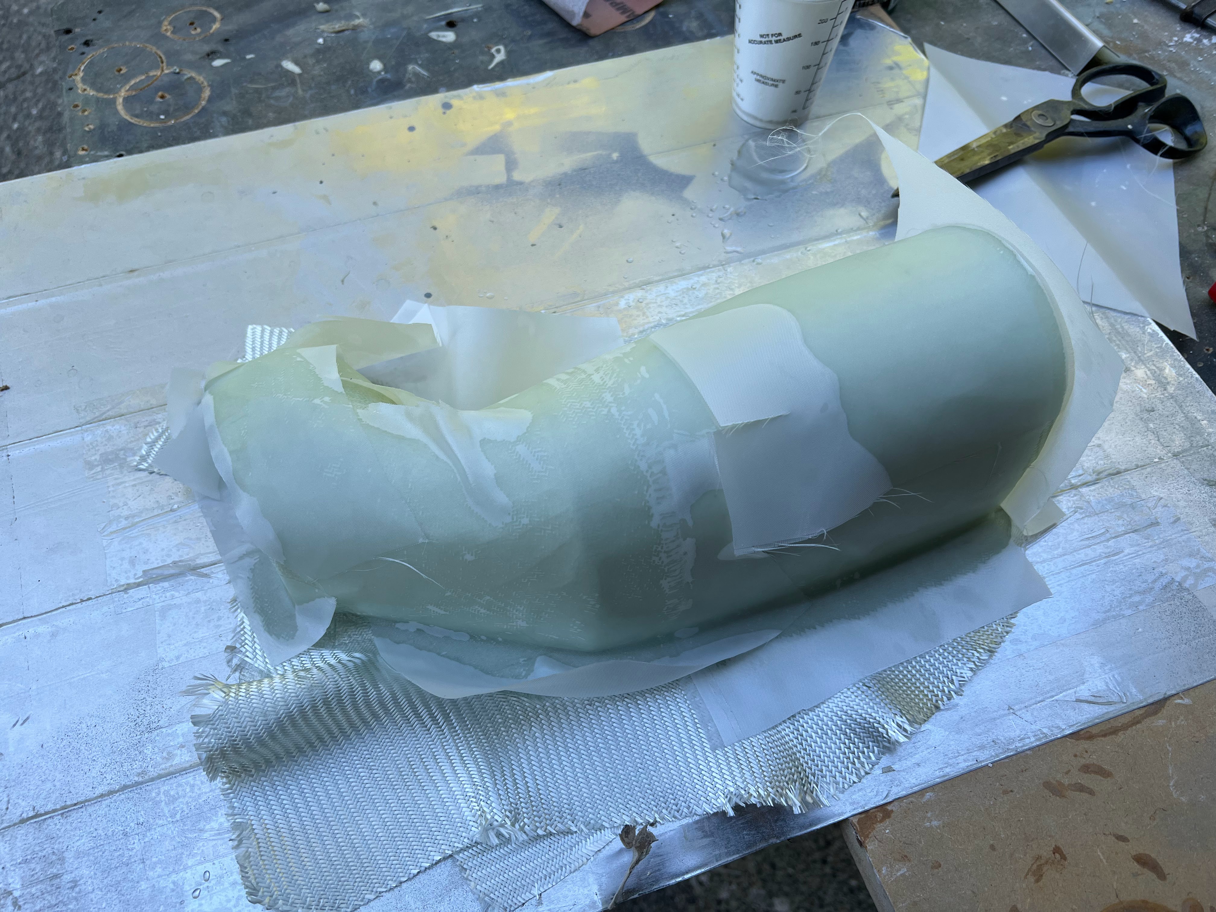

Part extracted from the mold with only minor mold damage.


Next:  I chopped off the rear flange (which was not usable... all the cloth was gathered there from the sides).  Put the part BACK on the mold (after some minor repair), and layed up 3 layers of glass on the rear, plus another layer on the top 2" to bind it all together.  Then another 2 layers on the leading edge to make it stronger as it will be sitting in the airflow at the front and want it super stiff.k

Part came back out of the mold with a little bit of poking and prodding.  It now has a new back and reinforced front.  Next is to make the bottom.


My plan is for the bottom to slip over the top.  I will bond them together with resin / cabo and cleco.  Once dry, I will put another layer or two of glass over the seam.

To make the bottom fit over the top, I have to build out the bottom slightly.  The glass thickness is about .04.  4 layers of tape is about .012.  So I need around 10 layers of tape to build up the edge enough that the bottom will slip over the top.  The only place this is critical is the rear as the back has structure.  All the rest of it will just conform, but figured I would try to do it right since I was already at it.

Bottom layed up.... fingers crossed.


Back extracted from the mold after lots of gentle nudging.


The sides need to be trimmed down obviously.

The first mold is very heavy and strong, which made it easy to get the part out.  I am somewhat worried about the foam mold.  It is fairly strong, but much more fragile than the first one.


Top and bottom temporarily fit together.  I think this is going to work out just fine.

I have been staring at how to mount this to the side of the plenum for quite some time.  I want it to be removable.  Since the beginning have been planning on using 2 of the 3 bolts that hold them plenum sides on.  Dawned on me the other day to use the holes that hold the top on a well.

So the plan will be an aluminum bracket (probably 0.063) that will go between the top and bottom mounts.  Then I will position the intercooler plenum, and both bond and rivet it in place.

After a lot of staring and wondering what to do, and talking to a hanger mate about his project I thought about 3D printing the forward plenum.  Talked to a friend that used to teach 3D modeling and printing at a local high school.  He accepted the challenge to design these up for me.


Ordered a test part through Xometry - which claims to be the uber of 3D printing.  Ordered on a Sunday with their slowest / cheapest option.  Shipped Thursday from MI via ground.  The top and bottom were $297 USD including shipping.  I checked a number of Canadian 3D printing shops, and the cheapest price was $500 CAD.

Parts arrived...


There is a small amount of interference at the front between the bottom and top of the plenum.  This should be easy to fix.


Rough positioning to see how it fits.  There will be a 0.063 plate that the entire assembly is attached to, so it will be offset outboard.  Also planning on an air gap to protect it from the heat after shutdown.

Plate made and clecoed in.  Duct clecoed in.  Nothing is final final, as I need to make a few filler plates to make everything be perfect.


Honestly, I think its pretty good.  You cant see it in the photo, but there is an air dam that comes out from the duct into the fiberglass inlet to channel the air either to the intercooler or cylinders.  I like this way more than my crappy fiberglass parts.  Need picture with cowl off.


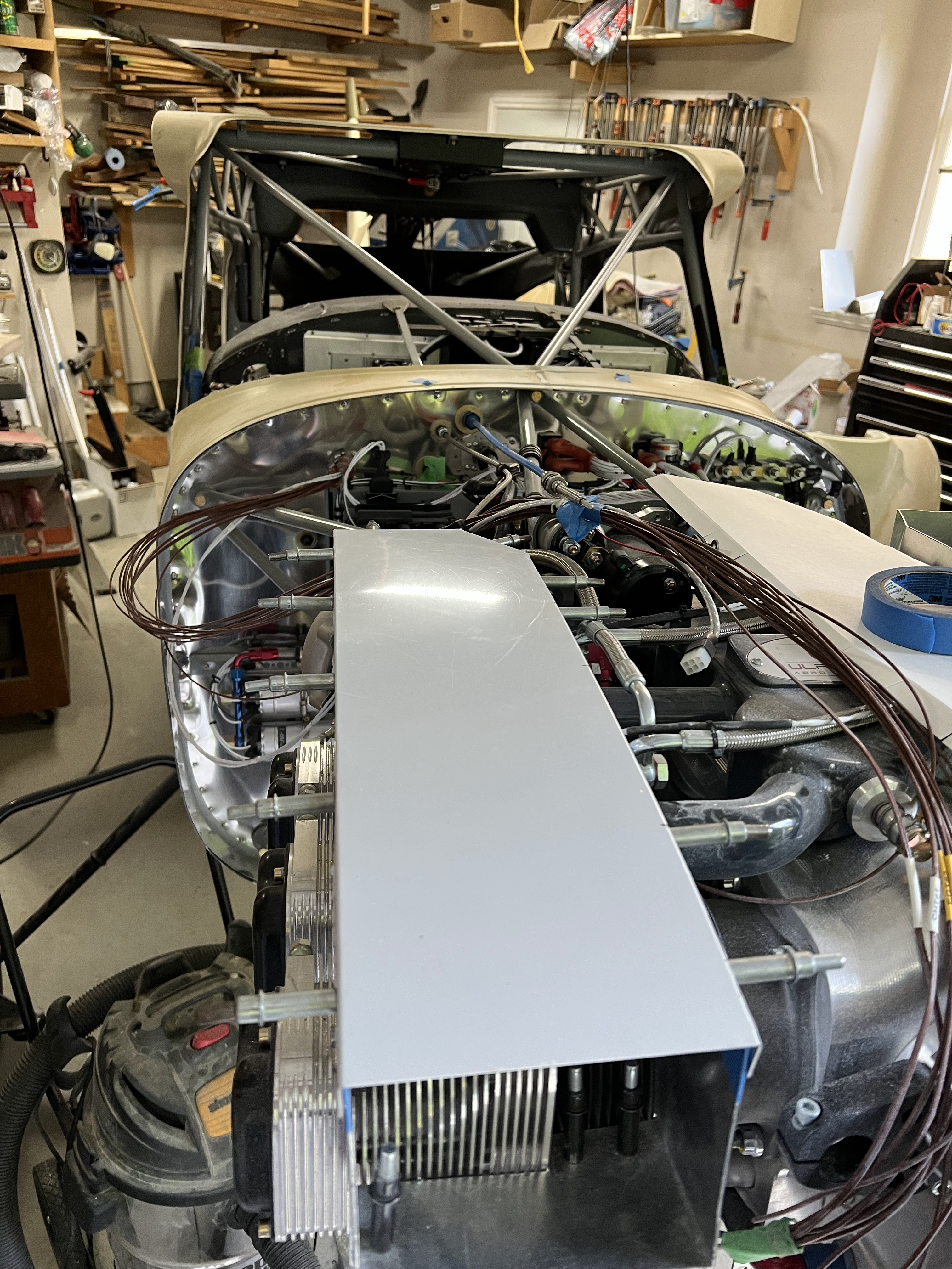
Almost all of the baffles and ducts are fit.  3 small ones to go, and everything is rough installed.


All done and fits.  Had to trim the cowl a bunch... but its done done!


Engine Plenum / Baffles

 All UL engines come with what I call 'baffle blanks'.  They fit the engine, have sides and a back.  They are cut down to fit the specific installation.

Current plan will be to trace and cut the outside (cylinder head side) out of a scrap piece of aluminum, fit it small, and use the paper clip trick (big paper clips along the top, put the cowling on and push the paper clips down using the top of the cowl) to find where the two meet.  From there, leave somewhere between 5/8" and 3/4" of gap, and cut the blanks to fit.

From there, make a top that screws into the blanks and forms the plenum.

Then the trick will be to go from the baffle blanks to the air inlets.  Tentative plan is to use multiple pieces of MDF to bridge the gap between - shape and form, and then use them to make fiberglass inlets that meet up with the cowl.

To make it more interesting... the UL engines dont need as much cylinder cooling as a Lycoming.  I do not want to change the profile of the cowl, so the plan is to use the excess inlet area to feed the intercooler plenum by running scat hose down the outside of the plenum and down into the intercooler.  I want to use as big a hose as I can - hoping for 3".

That is the plan.  Now to see if it is valid.

This is what the baffle / plenum blanks look like.


 Made a temporary side out of the form for the top of the cowl, and put a rough cut in it, and put on the top cowl (wood spacer installed on crank to properly position cowl).


Not bad for a first cut.  Its about right at the front, and too short at the back.  But thats fine... and exactly what this piece is for.


The front is where it gets interesting.  I had to trim 3/8" off the side.  There is very little room between the inlet and front of cylinder.

I took at guess at the plenum side, and I guessed to short.  Temporarily built the template up with duct tape so I could get paperclips on to get an accurate measurement.


Then transferred it to card stock for a template.


Then cut the plenum sides / back and fit it to the engine.


Cowl put back on to check for fit.


The good news is it fits.  However the cowl opening / plenum opening do not align.

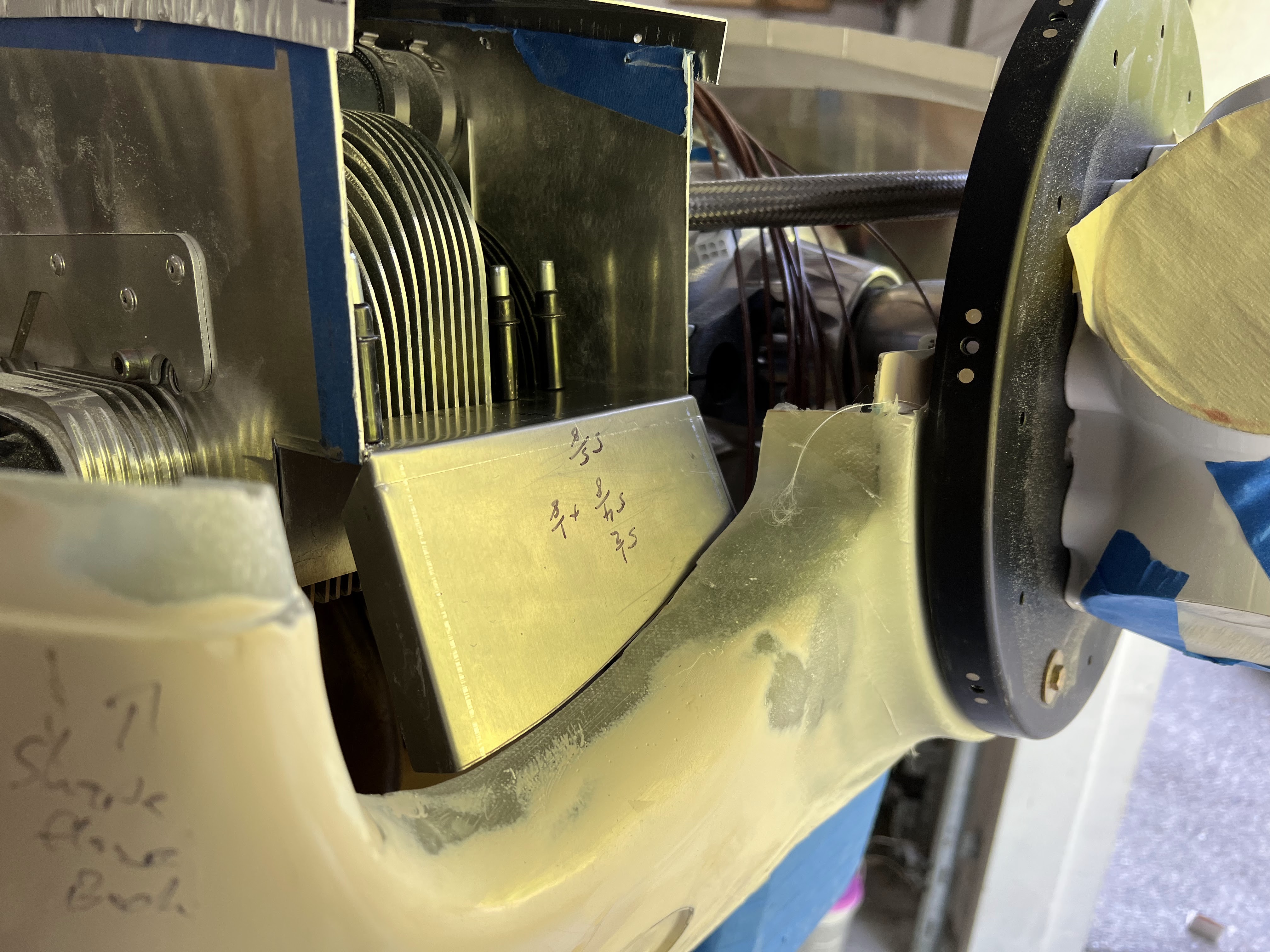
My plan is to use the outside portion as the inlet for the intercooler (on both sides).  The cowl opening is going to need modification in the inboard side of each inlet - both for the prop, and engine cooling.

Air inlet for Intercooler:  So I got this started.  The outboard side of the cowl inlet is hopefully to be used for the intercooler.

Below shows the portion I plan to use (the MDF piece).


The intake will run aft and up to clear the cylinder heads.


3" flange will go on the back.

Trying to save money, I decided to use drywall mud to fill all the gaps.  I underestimated how much I would need.  This is going to take a lot of sanding...  My wife pulled into the driveway as I was doing this and yelled "I want to play!".  She loves crafts...


And its going to take a long time to dry...

Going to make the left hand side differently when I get to it.

The left hand side baffle blank is considerably longer than the right - which makes sense as the front cylinder is farther aft.  Doing the same process.  Making a piece to match the blank out of scrap aluminum and will rough fit, then get the exact distance using paperclips.

Left hand side went much faster... and I got it a lot closer than the first using distances from the right side as a staring point.


Transferring to baffle / plenum.


Both plenums / baffles are in.  I had to hang the prop and see how it all comes together.

Next is tops.  I figured I am going to make them full length for now, knowing that I will probably be shortening them at some point.


Finally got around to making a test top out of aluminum.


I have only put a couple of shrinks in the flange, but it is following the top of the baffle really well.  I think this is going to work.

First one drilled and clecoed.


The inboard fasteners will be at odd spacings due to the intake tubes, fuel lines, injector wires, etc.

Onto the inlet ramps.  In my effort to keep the cowling looking 'stock-ish', I need to transition the air up and into the plenum.  Have been starting at this for awhile.  I took inspiration from how my Dad did the inlets on the Emeraude.

As usual, started with a paper template.


And then made it out of aluminum.  Only difference is the aluminum piece has flanges on the forward portion.  My hope is to tie these into the top to make them stiffer.


The front of the cowl is drooping slightly as its only held in by clecos - so probably some more trimming down the line, but this was the basic plan to start.

The top ramp is going to be much more challenging I think :-). 

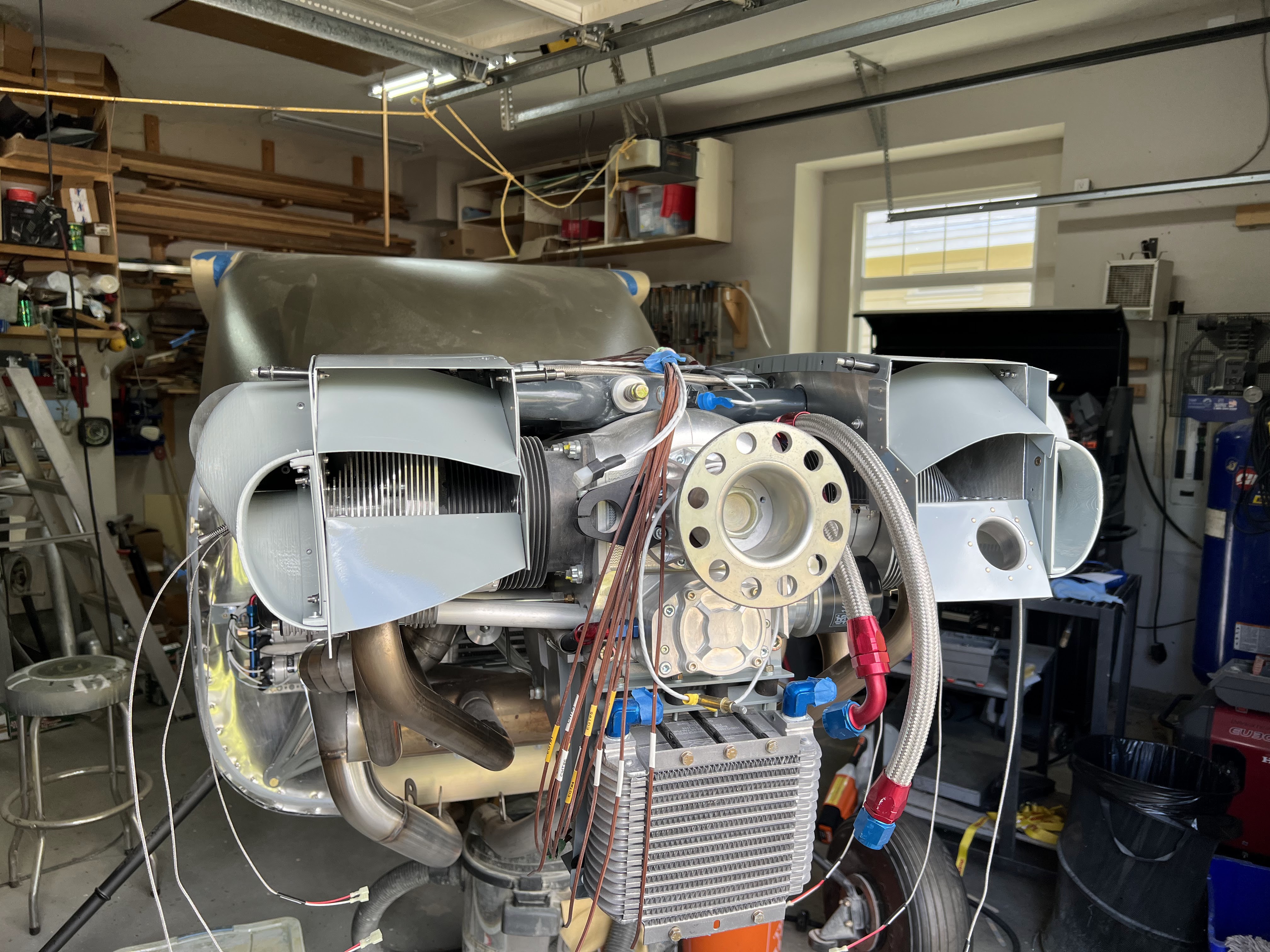
So fast forward a whole bunch of months... Like more than 6 months... and all of this is DONE.


Just need to connect the SCAT tubes from the forward plenum's to the intercooler plenum.


Wednesday, 13 March 2024

Certificate of Registration

Yesterday was a good day - received the Certificate of Registration for C-GVSW.


I submitted all the paperwork on Sun, Feb 11, and received the CofR on Tue, Mar 12.  Usual turn around time is ~2 months.  But the real win is they accepted all the paperwork first time!

I had heard horror stories about this, but it all went pretty smooth.

It's now a REAL airplane!  But in pieces... but not for long!

Sunday, 21 January 2024

Boost Controller Relocation

The 'only' (current) Sportsman flying with the UL Power 520T had an issue come up approx a year ago where the boost / manifold pressure would fluctuate.  I was fortunate enough to be around and help him troubleshoot this, and more importantly understand how the system works better.

The Turbo is powered by the exhaust (obviously)... But the amount of exhaust gas that hits the turbo is regulated by the waste gate, which is essentially a valve.  There is a spring in the waste gate that 'normally' regulates when the valve opens to start releasing pressure as to not overboost the engine.  The standard spring will fully open the valve at 3" HG above ambient which is about 6 PSI.

Enter the Boost Controller... The Boost Controller 'fools' the spring on the waste gate to allow turbo to spin faster and deliver higher than 3" HG / 6PSI to the intake.  There is a pressure sensor on the ECU in the cockpit, determines what the Boost Controller needs to do.

Below is from the UL manual... and shows the connections.


The boost controller is essentially another valve.  It connects the pressure of the intake manifold and the waste gate.  When the Boost Controller is allowing the turbo to spool up, ONLY those two lines are connected.  The 3rd port on the Boost Controller is a vent.  When an overboost situation is coming (IE Full Throttle) the Boost Controller vents the pressure from the intake manifold to let Waste Gate open up and drop the speed of the turbo.

The target pressure max manifold pressure is 39.5" HG, or roughly 20 lbs of boost.

In the case of the 'other' Sportman...

  • The problem just started on day.  Nothing had changed (IE ECU firmware) that would have precipitated the issue.
  • At full throttle / boost, the engine would start surging... 1 to 2" HG surge.  Pulling the throttle back would stop the surging.
  • Disconnecting the Boost Controller would stop the problem.  However, now you are limited to about 33" HG of manifold pressure.  The turbo is not working to its intended potential, but no surging.
  • Many troubleshooting steps were taken.  
  • UL sent a new boost controller, as well as a new ECU with special firmware.  They changed to update rate on the boost controller from 30 Hz to 10 Hz.  This did change the problem and make it not as noticable, and the surging delta of inHG was less, but the problem remained.
  • The eventual solution... move the boost controller.  In this install, the Boost Controller was installed low on the pilots side of the firewall.  The pressure lines went up to the top of the engine for the intake, and to the waste gate.  The theory is they were too long.  Relocating the boost controller completely corrected the issue.  The original ECU and Boost Controller were reinstalled.
So after all that... I am moving the Boost Controller.  I installed the Boost Controller on the cold side of the firewall, right beside the ECU.  The manual actual says to have it in a vibration free location, and I wanted both the red boxes beside each other.  Oh well...


Not the fanciest bracket, but it should work.  It's now very close to the intake manifold and waste gate.  The problem is I have to extract the harness from the cockpit bundles and fish it through the firewall and dress it in.  There are a lot of cable ties to cut...