Search This Blog

Sunday, 11 September 2022

Cowling and Extension - Part II

With the mold made, next step was to extend the top cowl.  My plan (such as it was / is):

  • Wax the inside of the aluminum
  • Scarf the cowl
  • Place a layer of peel ply against the aluminum (to get a nice finish of the end result)
  • Build a jig to hold it all together upside down to allow for rolling pressure, etc.
  • 4 layers of glass / resin, with another piece of peel ply on top (which is really the bottom)
  • The gap to be filled is 11".  The first layer is 12", 2nd 12.5", 3rd 13", and final is 13.5.  That should give a good bond (I hope)
I cut the glass and peel ply on our pool table (because no one really uses, it, right?)


Here is the contraption all assembled and ready to go.


The error that I seem to have made was hoping that the peel ply on the aluminum would stay put.  It did not, and I got puckering in the corners.  No matter what I did, I could not get the glass to sit on the aluminum.  Further, I had significant resin bubbles that I could not get rid of.  I kept laying the glass down hoping it would work its way out, and it just kept getting worse.  Watching the clock, I finally got desparate after the final layer of peel ply and very quickly cut a big piece of bleeder material, layed it on top, and rolled the heck out of it.  Thankfully that resolved about 90% of the bubbles and left a reasonable finish.


(above pic is with the bleeder removed)

Next step will be to disassemble, remove the peel ply, and see what I have.


Turned out OK.  Going to be lots of finishing work to make it look seemless, but the profile is what I was hoping for.

Need to do a rough cut on the overhang, and start the mold for the bottoms.  I am going to do these one side at a time, and then figure out what to do about the air exit bulge.

Starting on the lower cowl sides and bottom - left side first.  I switched to .025 aluminum fro .032.  Much easier to bend, and the bottom radius is much tighter.

Same process.  Jig it up with the same aluminum angle braces and get it to sit right, then insert the aluminum and cleco it in.


Next is chamfering the edges and jigging it up to lay the glass.  The profile on the firewall side is good, but there are some gaps on the forward side the will need filling later.  I think this is unavoidable.

The upper and lower edges are not cut to the final profile yet.  Just trying to get the shape right.

Mold ready for glass


Layup complete


Upper and lower cowl on the airplane.  They line up OK.  Going to need some finessing on the transitions, but that is just filling and sanding.  Overall, mission achieved.


Right side jigging and layup


After removing the form and putting it back on the fuselage.


Next will be to reinforce the outside (where there is no overlap) to stiffen everything up.  Then will be the air exit ramp.

Started with the top.  Ended up using a 2" drum sander barrel by hand, with a separate sanding block to get rid of the gel coat (or whatever the surface is that came on the cowl).

2 layers of glass.  1" strip, followed by a 2" strip. A lot of this will be sanded off once cured.


The peel ply looks all blotchy as I added a 2nd layer to soak up the excess resin.

Overall I am happy with the progress and outcome, but this is going to take another month or so to make it look right.  I think I have a solid foundation, but there is going to be a lot of filling and sanding.

That is enough for this post... Part III to come.

Friday, 2 September 2022

Cowling and Extension - Part I

 For weight and balance purposes due to the mass of the UL engine, it has been pushed out 10.5".  Francois did a lot of calculations to come up with that number.  It should allow full loading of the baggage compartment.

But this means that the cowling needs to be extended.

After thinking about this for a long time, the plan will be to cut ~4" off the cowl on the aft end, bridge the gap with and aluminum mold, and then add 4 layers of cloth it to bridge the gap.

First step in that process is to center the cowling on the crankshaft.  The inner diameter of the cowling at the crank is 8", and the crank itself is just over 2.75".  Make a disk out of MDF, split it in half, and then temporarily attached it to the prop flange.


Because it is not supported at the back, there is no way to line it up properly, so I dont see any way around just cutting off the back and hoping for the best.


3.5/8" marked off to cut.

On the bottom, I left the scoop in tact with the hope of extending it.  So in the bottom, I only cut off the sides, plus about 4" off the bottom.


Initial test fit.  The back 3 5/8" of the cowl is clecoed to the fuselage, using the holes on the cowl flange intended for the firewall mounting.

Unfortunately it does not line up. the corners on the top half are pushing out and not following the correct line.


So I believe the solution is the overlap the seam between the top and bottom halfs (temporarily) to get the right profile on the edges.

I mounted all of my 22" long aluminum braces.  The theory behind 22" long...

  • The gap to fill is ~10"
  • I need 2" of scarf on each side (14")
  • 2.5 additional " on the back side to pick up the fuselage to carry the line.  16.5"
  • Another 6" forward to support the cowl to get an even transition.
Starting in the middle and working my way out on each side.  All of the braces are numbered, as is both the fuselage and cowl.


Using this method, I successfully followed the curve.  And my pushing the forward cowling piece down, the whole curve is lining up.

The trick will be redoing the goggle - but that is a problem for another day.  This shows the amount of overlap to get everything to line up.


The plan:  do the top cowling and fit it back on the airplane post fiberglass / scarf joint.  Then use the same method on the bottom (starting at the bottom and moving my way up.

For the mold, I am going to follow Ted's advice.  Aluminum.  I bought a 60" x 16" piece of .032.  Lined it up in the center, and took off the two center braces and drilled the first, and worked my way out again.  Had to trim the aluminum a bit.  17" wide would have been better in hindsight.


The only issue is the .032 does not want to bend, so its pulling out on the sides.  Plan will be to made a frame for it to sit in while I glass it.

Next is to take it apart and scarf the joints as close to 50:1 as I can get.  Going to put peel ply on the aluminum to try and get a decent finish.


Monday, 29 August 2022

Engine Installation - Part II

 While I was waiting / saving for the engine, I planned ahead on component mounting, firewall layout, etc.  The bad news is almost everything I planned had some kind of issue.  The ECU is not exception.

My original plan was to mount the ECU on the right hand side of the 'shelf', forward.  Well, the cannon plugs and wiring is to large to fit under the right side avionics tray.

Original plan


New plan


I turned the ECU 180 degrees, and moved it aft about 3".  This was easy, except the UL aux box is mounted under the shelf with captive fasteners on top.  Made a quick drill guide and done done.

The current top of mind issue is the firewall passthrough.  The wire bundle is ~0.85" across, but the connector is just shy of 2" in diameter.  So you need a 2" hole to get the connector through as the engine is prewired.

Talked to the US distributor, and a local gent that has a UL on a zenith.  Consensus is to make 2 C shaped pieces that interlock and cover the 3" hole, and leave 1" for the wires.

My last attempt at cutting stainless was poor, so I checked out SendCutSend.  I very quickly designed a part (using their standard parts catalog) that would do the job.


Minimum order is $29, so I ordered qty 14.  Each of these will be cut so they overlap.  Total of $32 USD including tax and shipping (to my US post box).  

Ordered Saturday, production started on Monday morning.  Looked like they were going to ship on Monday, but then their progress meter got stuck at 60%, and the estimated ship date went to 4 days later.  Guessing they are out of material or something like that.

Parts received.


I cut 2 disks into C's, and split the firewall passthrough in half and assembled the whole thing.


Works as intended.

Next steps:

1. Plan out engine wiring integration.  John Wood told me about this pretty good free / open source software called QElectroTech.  So far I am quite impressed.

2. Cowling.  Need to get this done before the weather turns cold.  Ideally I am waiting for the prop to arrive so line up the spinner.

3.  And a lot of everything else...


Thursday, 11 August 2022

Engine Installation - Part I

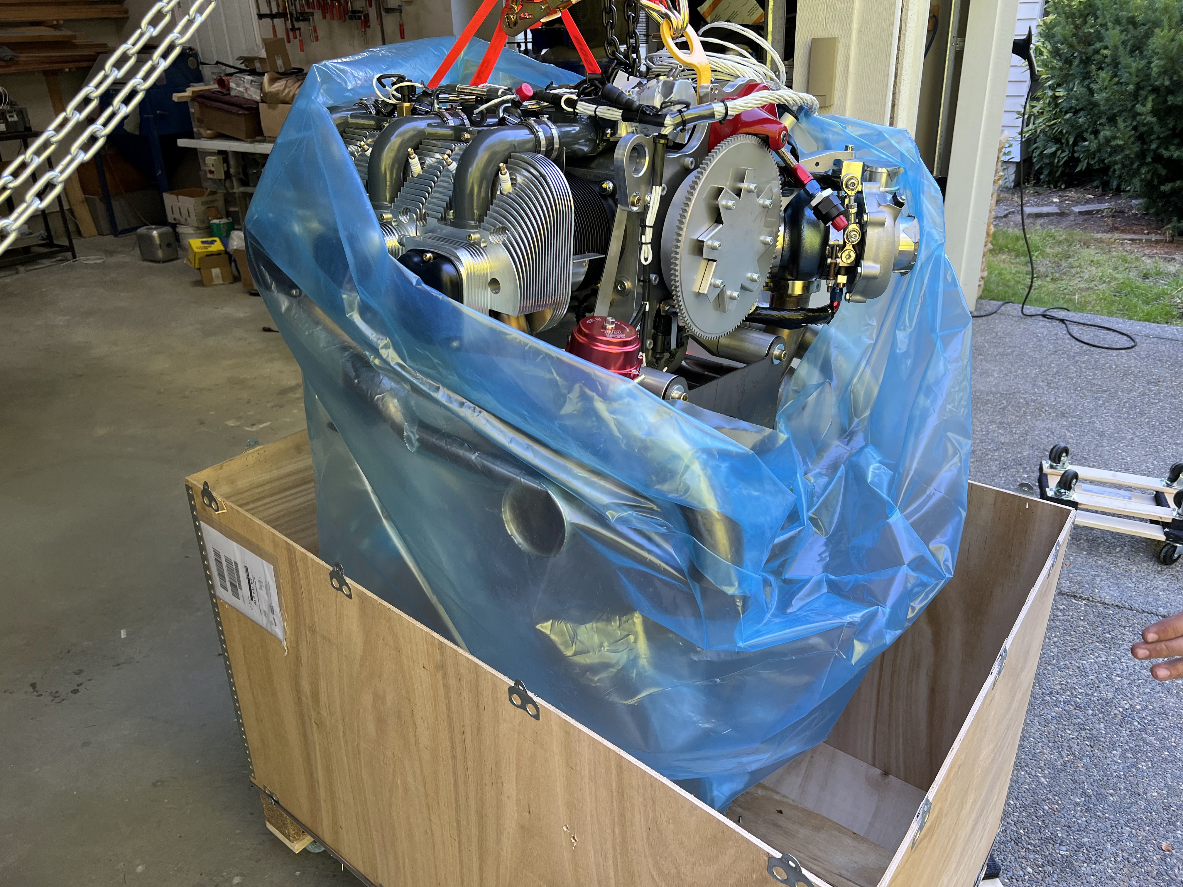
 Very cool evening.  My son and I installed the UL520T on the airframe.  Took around an hour between freeing the engine from the crate, lifting it, and assembling all the mount hardware.

No major issues.  The only thing that needs some follow up is an oil line either to or from the sump is too close to the engine mount washer.  Will follow up with UL and find a solution.

The engine wiring looks pretty straight forward.  2 large cannon plug connectors to the ECU, and various fanouts for power, ground, coils, regulator, etc.  That will be a project for next week.


Next challenge is fitting and extending the cowl.  Hope to start on that next week.  Waiting for the prop.  Has been ready to ship since late June, and paid for since mid-July.  But I know the required spacing, so I should be able to start.


Tuesday, 9 August 2022

Instrument Panel - Part III (Wiring)

Now the wiring begins.... I both love and dread this part.  Love it because it makes things work, and dread because compromises will need to be made.

Step 1:  Electrical bus(ses).

Target is 3:

1. ACM - which includes avionics, lights, pitot heat, etc.  Everything that the ACM powers, which is everything but engine.

2.  Engine bus.  Stand alone bus for the engine, using breakers.

3.  Everything else bus.  This will be fuses, and for things that dont really matter - like seat heaters.  This will be the last priority.

The output of the two batteries goes to a central point, which is the current shunt.  This shunt will measure the total input / output to the batteries and will be inclusive of everything.  From the shunt, power goes 3 ways - to the ACM, Engine Bus, and to a fuse panel.

Fuel Pumps

The UL Power ECU has the provision to 'control' the fuel pump (or pumps) via a relay.  The ECU drives the coil on the relay (Fuel Pump Control Relay - FPCR), so it can turn the pumps on or off.  This is useful when on the ground working on things.  The system will pressurize, then the pumps shut off.

However, what if the relay fails?  So my fuel pumps switches have an 'auto' position (which goes through the relays) and 'force', which does not go through the FPCR.  Overkill?  maybe.

Everything else engine needs to wait until it arrives - hopefully in late May.

From a wiring perspective... 2 power feeds from each of the pump breakers.  1 feed goes directly to the switch, one goes to the FPCR.  The center position of the switches goes to the pumps.  The pump wiring is on a connector as the whole fuel pump tray is removable (kinda - have to take the header tank out first).


Header tank sensors.

Well this has been fun.  The sensors I bought from Radiant are cool, and I tested them very thoroughly with water to ensure they do what they should do.  But their connectors are, lets say, interesting.

The sensor is connected with a USB cable.  The head unit (of which I have 2) has the power connections.  Plus the cable lengths were way too long.  So I shorted everything up and put them both on one connector.


They are temporarily wired to power off a breaker to verify the wiring and connector.  Debating whether to power them from the ACM or a breaker or fuse.  Probably the ACM long term.


They flash red when liquid is not present.  Obviously the tank is empty, which is a good sign.

Radient recommends siliconing the LED's into the holes.  Not sure if I am going to do that, or make a mount.


ACM and Pre-Built Harnesses

I love the ACM.  I love the harnesses.  I have to figure out how to tame them.

To start, I plugged everything in.  No wires are tied in anywhere.  Just wanted to get the lay of the land (so to speak).  Holy crap, its a lot of wires and I am nowhere near done yet.

Dont judge me based on these pics.  Please.


The plan is to figure out where everything will go, then take it all apart and finish the trays and brackets, then reassemble for good. But I have to build the aircraft front, rear, and wing harnesses.  Everything is ordered to do that.

Main Power Distribution

OK - this is a mess.  But you have to start somewhere.  Again, the purpose was to figure out what goes where.


Two EarthX ETX900 batteries, two master relays with flyback diodes.  Each battery can be switched in or out.  This is all pseudo temporary, but it works.

The output of the two relays is bridged together, and the starter will come off here.  From the bridge point, goes to the main shunt with 6 gauge wire.  From there, goes to the ACM and engine bus.  The battery, aircraft frame, and engine all tied to a single firewall ground point.  Also a 10 gauge wire to the avionics bay ground bus.  This may need to increase to 8 gauge.

Engine Bus

As the ACM shies away from anything 'engine' related, I decided to have breakers for everything engine and fuel related.


10 gauge wire coming from the main current shunt on the hot side of the firewall.  It passes through a Hall effect sensor, so I will know (in theory) the current draw of everything engine / fuel related (but I won't know what is drawing what - just the total).


The Hall effect sensor is mount under the starboard avionics tray.  This may have to move simply for serviceability.  It will be very difficult to change - if not impossible.  On 2nd thought, if the MFD is removed there is a clear shot to it, but all of the wiring is not yet installed so that may change.  Time will tell.

Harnesses to build

- Aircraft front:  Comprises of prop controller, taxi lights (which will go to the wings - but that is a different story), cabin lights, panel fans, belly strobe, elevator trim.

- Autopilot servos:  These are pre-built from Advanced, need to be terminated on servo end.

- Sticks and flaps:  PTT, AP disconnect, IDENT, flip flops, Audio Panel switch, flap position potentiometer

- Wings (aka Aircraft Rear):  Pitot heat, landing / taxi lights, nav / strobes, fuel transfer pumps

- Engine sensors:  EGT, CHT, Fuel Pressure, CANBUS (to ECU, which has a large number of sensors), fuel tank sensors, etc.

The panel has taken a bit of a back seat due to waiting for a new panel from Glasair.  Should be here August 9th, then I have to recut it all over again.


Autopilot / Servo Wiring and Avionics Trays

 As part of my avionics package from Advanced, I purchased their pitch and roll servos.  All the servos come from the same manufacturer... also purchased the servo mounting tray from Glasair.

All of the brackets have been fit, fasteners drilled, and I added a few lightening holes in the tray itself.  While I was at it, I finished the left and right avionics trays that mount to the cage.  Lots of drilling and fitting nutplates.

All these were put through aluimiprep, alodyne, primed and painted.  The paint is PPG, and matches the grey of the cage.


Remote radio unit repositioned slightly due to cable length.

Everything dry fit.


Installed and wired.  I was SOOO careful to not mix up the wiring for the pitch and roll servos, and guess what - I cut them the wrong lengths.  So I de-pinned the connector and switched everything around.  


Left and right avionics trays are finished and nut plates installed.


The top picture is the left side tray (the IBBS is mounted under the tray). The next two pics are the right side tray.  I have not mounted the audio panel or Hall effect sensor yet... waiting for hardware.

I am going to need to raise the EMS and Audio Panel to clear nut plates underneath (they overlap each other slightly).

Handful of things to do before they are mounted - and actually will not be fully mounted until the firewall comes out.  2 holes need to be drilled in the forward tabs for the trays.

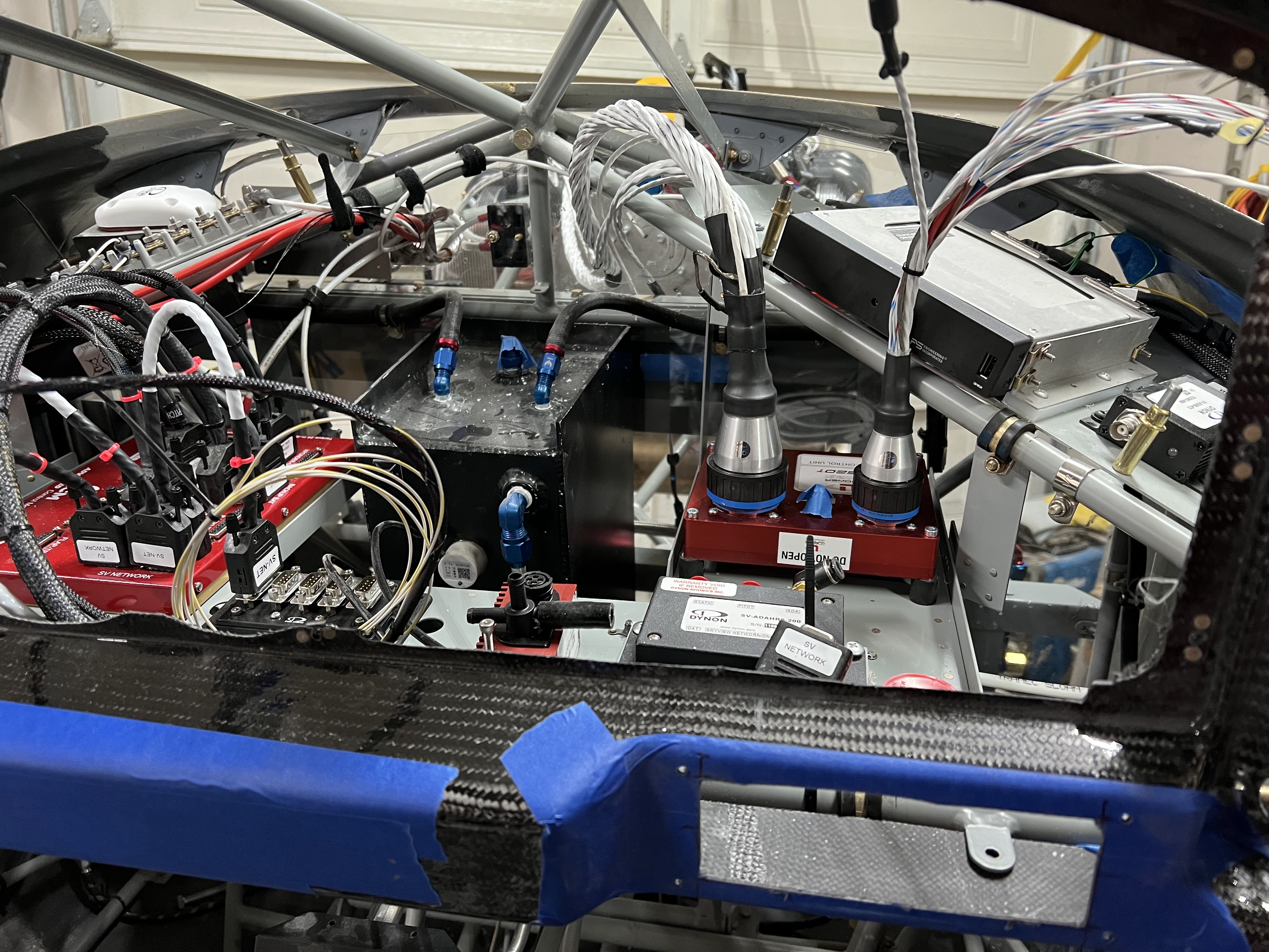
Next is the big tray that will hold the ACM, Skyview Network Hub, ECU, Boost Controller, Aux Box, and ADHRS.  I very quickly put it together to see if it was going to do what I wanted, with stuff I had in the shop.


Now that I think this is going to work, have gone back and finished drilling it, and making a few modifications, plus adding lightening holes.  Oh, and drilling for fasteners.... ugh.


After finishing, ready to mount.


Installed with most components present.


Lots of wiring still to do, but progress is definitely being made.