Search This Blog

Wednesday, 30 November 2022

UL Power - ECU Wiring

I thought the UL ECU wiring would be simple, and in some ways it is simple.  But as always, the devil is in the details.

Power:  The ECU has 6 wires that all need to be attached to an ECU switch.

Ground:  The ECU has 5 wires that go to ground.

FPCR (Fuel Pump Control Relay(s)):  The ECU can control the pump(s).  I opted to do so, but there is a 2nd bypass circuit around the relays just in case.

Ignition:  Circuits for left / right or 1/2 coils to switches (or a standard key switch).  Grounded they are OFF, open they are ON - just like a mag.

Aux box:  Provides ambient pressure.  Plus other things, but this is all I am using it for.

Boost controller:  Control line from the ECU to the Boost Controller, plus power and ground.

CAN-bus:  Data lines to grab engine data via CAN.

RS-232:  Separate RS-232 connection for an EFIS feed, or to use the UL-READ software.  I need to order this cable.

Discrete engine inputs:  Separate inputs for Engine RPM and fuel consumption.  I am not using these, as they are provided over the CAN-bus.

Dummy lights:  2 LED's.  1 for 'check engine' (which indicates a sensor fault), and 1 for 'low battery'.  I planned for both of these in the panel.  The ECU only provides a ground to activate these LED's, power is separate.

The above is the basic lay of the land.

Current schematic below.


At present, everything is wired except the key switch.

The challenges:

  • The ECU is mounted on a tray forward of the instrument panel.  If it needs to be removed, take out the MFD, remove the two harnesses, loosen the bolts and its free.  You should be able to do all this sitting upright in the seat.
  • Making the above happen is a challenge.  I had to route all the wires in two consistent bundles (one firewall forward, and one for the cockpit interconnects) and not running in 4 different directions.
  • To do so, I fabricated some wiring 'braces' that everything is tie wrapped to.  But its all very condensed. Hopefully this works out.
Progress:
  • Everything is wired for the ECU, and it powers up (the LED's flash upon startup).
  • The next big step is to see if the ECU connects to the CANBUS on the EMS221.
  • The wires are not in their final position.  I want to make sure everything works before doing the final tie wraps (hence no pictures, it looks pretty ugly right now)
What's left to wire:
  • Magnetometer:  Cable is run, but needs to be shortened (ordered it too long)
  • Fuel tank probes.  Wires to the EMS, needs to head out to the wings.
  • Sticks:  Sticks themselves are wired, just need to route them and connectorize from the ACM (plus the pull downs from the audio panel, com, and ACM aircraft rear connector
  • RF / antennas:  VOR, 2xCOM antennas.

Probably forgetting something, but its almost there.


TO/GA Button

I had figured I would eventually figure out where to wire the TO/GA button (Take Off / Go Around).  That never happened, so I needed to ask Advanced.  Well, that feature is not available yet - coming in release 17 (current release is 16), with no planned delivery date that they would commit to.  Well I am not ready to fly yet, so no big deal.

The button needs to be wired to one of the PFD inputs on the Aircraft Rear connector:

From the Advanced Manual:

Will use PFD2, pin 14.

I was really nervous about opening up my AC Rear harness, but of course it was a non issue and took 2 minutes.


Last step is testing it, but that will have to wait until the displays are back in.


Dynon EMS-221 Wiring

As Advanced Flight Systems is part of Dynon, it stands to reason that Advanced would use the Dynon EMS (Engine Monitoring System) unit.  Dynon has 2 flavors - the EMS 220, which is the standard unit - and the EMS 221, which has CAN-bus connectivity.  I need the 221.

The EMS-221 has 3 connectors:

  1. DB9 for the Skyview Network connection
  2. DB37 for all of the engine wiring (except CHT and EGT)
  3. DB25 for CHT and EGT probes
1 and 3 are straightforward.  2 is interesting.

The UL ECU passes most of the engine data over the CAN-bus connection.  From the UL manual...


Bottom line:  There is very little for the EMS-221 to do, other than getting the CAN-bus data from the ECU.  Here is the pinout (only yellow items are planned to be used)


Basically current, voltage, fuel tanks, and CAN-bus.  I have a question into Advanced on whether or not I can use the 2 voltage pins, as these are on the ACM as well - so these might not be needed).


Everything is wired, except for the tank sensors.  Kinda need the wings for those...

I put the EMS on the bottom of the right hand avionics tray, thinking this would be easy to get to. Yeah, right.  Its not impossible, but definitely not easy.  Removing the ECU makes it easier.

Fuse Panel

I have a couple circuits that I dont want to run through the ACM.  Why you ask?  Well, what if it fails.  Or, what if the current draw is high and the function is not essential?  

Things that are going to be fused and not through the breaker panel or ACM:

  1. LED indicators.  2 for the UL ECU (Check Engine and Low Battery - the ECU does not provide power for these, only a ground to activate them).  Plus another for the Alternate Air Inlet on the airbox.  Dont need carb heat as the engine is injected, but need an 'emergency' air source if the filter gets iced up.  1A circuit
  2. Header tank warning lights.  If the ECU dies, I want these alive and functional.  Another 1A circuit
  3. Seat lumbar support.  It has a small pump and inflates/deflates the bags in the seat.
  4. Seat heaters.  I am a wus.  I like seat heaters.  These draw more than the ACM has capacity for.
  5. Other stuff down the road.  Will be nice to have a place to get power that is somewhat readily accessible.  2 spare circuits.
I found a really nice automotive style 6 fuse panel that is small and light, and has indicator lights as to their health.


The plan is to mount it on the starboard side of the fuselage, just above the rudder pedals on the side of the fuselage.  The original plan was to make a plate and attach it to the cage tubes with adel clamps.  Well, I hate adel clamps, and mounting it up there with the bulk of the avionics installed would be a nightmare - so I decided to bond the bracket to the fuselage.

The bracket is a simple hat shape.  The tabs pick up the holes in the fuse panel, and the bulk of the bracket will be epoxied on.  The below pic is the bracket clecoed in place, ready for bonding.


Because its winter here, I need enough heat to get the resin to cure.  Luckily I have a big heater in the garage, but it will cost me.  The bracket has already been fit to the fuse panel so it should just screw in once cured.  I waited until a relatively warm day (aka 10 degrees C) to do this.

Done and first circuit wired (power for LED indicator lights and header warning lights).


Wednesday, 23 November 2022

Instrument Panel Redo (Carbon Shroud Only)

 It's a long and sad tale, but I had to replace my carbon panel with a new one.  Which meant cutting and fasteners all over again.  Carbon fiber is itchy... do not recommend cutting it and then going to bed.

The good news is everything is faster 2nd time around.  In 2 evenings I had everything cut and most of the fasteners installed.  I have to make new brackets for the nutplates on the switch plates, because of the switch plate dimensions, standard nutplates will show the rivets in the carbon.  Hopefully this too goes faster 2nd time around.


I am finally (almost) back to where I was in April (its now August).  Still missing a few fasteners that will need to be riveted in later.


I have been wiring like a madman for the past 2 days.  The aircraft front and aircraft rear ACM connectors are done.  The trim and flap connector is done on the ACM end, plus the aileron trim wing bulkhead connector.  There is still a ton of wiring to do.  Like days and days more.  Plus the engine wiring integration (which should be relatively easy... famous last words).

Everything is working as before, except I have added some wiring.

  • Autopilot servos:  Not working.  The ACM says they are drawing power, but the Skyview network cant see them.  Troubleshooting with Advanced. Fixed and working.  Factory harness was wired incorrectly, and I missed it.
  • Recognition light.  Working.
  • Wing wiring to bulkhead connectors.  Working
  • Glareshield fans.  
  • Overhead cabin light
  • Compass light
  • Aileron trim.  Not tested
  • Elevator trim.  Not tested
  • Flap position sensor.  Not tested (potentiometer not yet installed)

The last piece to mount is the magnetometer.  I dont know why, but I have been dreading this.  Used some foam / glass test pieces I had and just chopped them up.  Simple and light.  The below picture is bonded to the fuselage.  The aluminum bracket is just for placement and will be removed.


Rudder Stop Plate

 The rudder was finished very early in the build - well, it was actually the first thing I build in 2016 (now 2022).  Need to fabricate the rudder stop plate, and check the travel / deflection.

Fabricating the plate was easy enough, following the manual.  Fitting it to the rudder was pretty easy as well.


I was worried about bending the ends, but that turned out pretty easy as well.  I took a piece of 1/8th flat stock and rounded the corner, then clamped that along with the plate to the bench and then just bent it with my hands.  Turnout out perfect.  The manual calls for a 15 to 20 degree bend.  The first one took 3 attempts to get it there.  The 2nd was a one shot deal.

I drilled the aft holes to 3/32 and put 3 clecos in, then mounted the rudder.  The target is 25 degrees of travel, +/- 1 degree.  However the manual calls for initial fitment without the stop pad.  My fuselage already had the pads in place, but I then did the SB to add the stiffener which required drilling out the pads and remounting on top of the stiffener.  So my initial reading was 20 degrees.

Again, the manual calls for taking 1/8" off the stop plate to account for the pad, which I did.  That got me to 23 degrees.  A bit more filing and I got to 25.


Both the elevator and rudder stop plates need to be cleaned, alodyned and painted.  I have NOT checked the elevator travel yet, as the horizontal stab and elevator are at the hanger.  That is a job for another day.

But the rudder stop plate needs to be drilled up to 1/8" holes, finished, and riveted.

Glareshield

 I keep waiting to simply 'install' something, that doesn't require cutting, drilling, grinding, etc.  After 5 years of cutting, drilling and grinding I think I'm due.  Well, today is not that day.

I bought my fiberglass glare shield from Glasair in January 2021, along with the panel blank.  I kind of assembled everything when I got it in March, and it didn't fit.  Well, that was just to make me feel good and I had lots of work to go until I needed to put it in.  That time is now.

After the issue with the panel misalignment were corrected, I HOPED it would just slip in.  NOT.  It does not fit at all.  Further, the instructions (which did not come with it either, but I found on the forum doc library) don't say anything about cutting.  After checking with a few builders, yes it needs to be cut.

Here is the starting point.


I made a paper template that is the same size (and non symmetrical shape) as the blank.


Next the template goes into the glare shield location.  I marked with a pen below the window opening, and then added ~1" after the fact, cut to the +1" line.  


In some areas I took off a couple inches, in others nothing.

The trick seems to be getting the depth of the glare shield right first, because that changes everything else. I worked on this in bits and pieces, where in hindsight should have focused on this first.

The big trick is getting around the cage tubes on either end of the panel.  That took the most time.

A fellow builder told me its like doing the windows... fit, mark, trim, fit, mark, trim, etc, etc.  I haven't done my windows yet, but now I know.


I cut too much off the aft glaresheild 'lip' on the left side.  So a piece cut off is being grafted back on....

Its basically fit now.  Needs a little bit more finessing.

Also to do:

  1. Find some muffin fans to install in the glare shield.  Need a fair bit of CFM, 12V, at least 6" with an attractive grill.
  2. Figure out how to wire them so they can be disconnected easily
  3. Tabs.  The forward part of the glare shield slips into tabs that hold it up.  2 recommended.  Aluminum, with a bend, bonded to the fuselage.
Fans.  Found some on Amazon (2 for $35 CAD).  They ended up being 4 wire computer fans... Pinout:
  • Black - ground
  • Yellow - 12 V
  • Blue - PWM control
  • Green - RPM
If you connect just ground and 12V, it runs at full speed.  The other 2 are not required.

To start, I marked a line under the glare shield where the panel to firewall struts are.  Had a nightmare I was going to hit run into them...

Then I measured up from the brow of the glare shield 10".  Centered the fan, and drilled a pilot.  I didn't have a bit enough hole saw (would need about a 4.7" holesaw), so I used the largest I had and then enlarged the hole on the drum sander.


They are not perfectly symmetrical, but darn close.  I doubt anyone will ever notice.


The fan covers are from Amazon as well.  $15 Canadian for 2.

Next is tabs...


It was recommended to clamp the tab in place.  Well, I fought with it for a while and finally just drilled and put a (waxed) cleco in to hold it while curing.  This also had the benefit that I could position the tabs and put the glareshield in place and ensure the front engaged the tabs.  They did...

Last two things are wiring and hardware to mount the fans.

The power source will be the ACM, which will be on the left hand side of the radio stack.  So the plan is to bring the wires down the left hand side with a 2 pin connector and end them somewhere that you can reach under the panel and disconnect with a minimum of fuss.


Tuesday, 22 November 2022

Flap Position Sensor

Ever done something that you know is (close to) useless, but do it anyway?  And spend way to many hours in the process?  Yeah, been there.

The Advanced system on the ACM flaps / trim connector has flaps, aileron and elevator trim - both motor drive and position sensors.  The Sportman has manual flaps, so no need for the motor - but I want the position sensor (which is stupid me thinks).  I had the sensor, so it was just a question of mounting and wiring.

I ran all the wires from the FLAPS-TRIM connector.  Aileron trim is run to the right wing connector.  Elevator trim bundle is curled up in the back of the fuselage, and the flap bundle was sitting in the middle.

The bracket for mounting the sensor is deceptively simple.  Mounting it (using 2 adel clamps) is the challenge to get everything to line up and have nothing touching.

If you are going to do this (don't), get the 1.2" sensor.  Where I mounted it needs about 1" of travel, and I set it for about 0.1" of slop on either end so its not bottoming out.  The 'arm' is just a piece of welding rod, bent.  Yeah, that took 3 goes to get a good one.

Cutting to the end... Flaps retracted


Flaps extended


Wired and labeled.  I used solder sleeves.  Don't know why, because I hate them.  But in this application they seemed like the right choice.  I didnt shrink wrap everything like I usually do because I know these will break at some point.


There is a loop in the cable for WHEN the STUPID 26 GA wires break, there is enough slack to resplice.


Monday, 14 November 2022

Prop Controller / Manual Pitch Change Switch

This entry is about a lesson learned, and creeping elegance.

When I layed out my panel, I put a spot in right above the throttle for the prop controller (which goes in a 2.5" standard hole).  What I FORGOT was the manual course / fine pitch switch needed for manual operation.

I dont have any room, and where I do have room it doesnt fit (too tall).  This is the wee beasty...


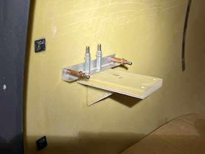
After much pondering, I decided under the throttle / instrument panel would work.  Its close to the throttle, out of the way, etc.  I could use 2 of the bolts the secure the panel to the cage to tie it in.

The first version was pretty crude and was not square.  The 2nd version was much better, but for some reason I decided the mount the switch on the face of the panel.  Once I realized that the mounting holes in the switch were threaded (6-32), I pitched that one and made a 3rd.

2nd version


3rd (and hopefully final) version


The ultimate position would be beside the controller, but I dont have room.  2nd best would be on the switch panel beside the throttle, but the switch is too tall for that.  The other consideration was to keep it away from peoples knees.  It is in the center of the airplane (lined up with the tunnel cover below).