Search This Blog

Friday, 6 October 2023

Prop / Spinner / Hub and Cowling

Lots of fun ahead.

I have been putting this off, because I know it will be a lot of work.  But the cowl, baffles/plenum, prop/spinner all have to work together and fit correctly.

First step is to put the brush mount on for the slipring.  This is easy :-)


The cowl has to be notched for the slip ring mount, as does my cowl alignment fixture.

Next I put on the hub, blades and spinner (temporarily).


I could not resist connecting the hub to the controller.  IT WORKS!

Under no load, the prop draws about 1 amp when moving. Full feather is pretty darn cool.


Installing the prop was simple.

  1. Add slip pickup mount bracket and pickup to engine.
  2. Put the bushings in the hub
  3. Mount the hub
  4. Put in the hub bolts (through the back)
  5. Attach the blades.  Blades are marked both on the hub and each blade.  Align the cam, and wind in the threaded hub
  6. Done...
Because the shop needed to be cleaned, I pushed the plane outside yesterday.  Gives you a very different view of it not in a confined space.


Next is the start cutting up the front of the cowl.  Opening up the inlets.


The goal is to open them up so the inboard side of the inlet meets up with the spinner.  I roughly got there yesterday.

Back on the plane, plus cut the opening for the oil cooler.  It needs to be a touch larger still.


I want to get the hub and spinner put away, and also have a working surface that I can sand against.  Made a ring out of 1/8" plywood, split it horizontally, hot glued it and slid between the backplate the cowl.  The backplate has holes in it, and I drilled through the ply and cowl for clecos.


Next... need to sand the cowl and get it ready for bonding foam, filler, etc.

After some emails and a call with Zach, not going to go the foam route - but epoxy and micro balloons.  Only slightly heavier, but much easier.  New plan :-)

After HOURS of sanding... yes, hours... everything is prepped and ready for the filler.  The gel coat was really thick around the prop flange.  Used 80 grit paper and an air powered orbital sander - but it still took hours.  I went to far as well, but thats fine as I saved the weight of the gel coat (at least that is what I tell myself).


The plywood templates have been wrapped in packing tape, and the clecos waxed just in case it runs down.  Plus the crank has been bagged.  Last thing is to cover the oil cooler just in case.

Used a mixture of West Epoxy, microballons, and a touch cabo.  It is no where near perfect, and going to need sanding and another coat.


Every time I tried to touch something up, something else got worse - so i just left it.  Once it is all dry (which will be quick with our temperatures) I will take it apart, sand it all flat, and do another coat.  No big deal, just more time.

It turned out pretty good.


Already have given it a light sand to knock off all the high points.  The face of the flange has some gaps, so the plan is to fill those, then put the plywood back on and fill again.

I thought the 2nd coat would be easier than the first, and it was not - due to some crappy prep.

On my plywood ring (that is covered in packing tape) I picked off the bits of resin that where on it.  Well, I didnt get them all and its not perfectly smooth and was grabbing on the large 12" putty knife.  Lesson learned - put on new tape on subsequent coats.  Also, the mixture was slightly runnier than before (not enough micro).  So more sanding is in my future.  Not happy.


Also... The face of the prop flange needed some cleanup as well (gaps between OLD edge of the cowl and the filler), so i touched them up and then put on the plywood ring.  There were a couple problems with this approach.
  1. When i put the packing tape on the plywood, there were some wrinkles.  
  2. I didnt put packing tape all around.  The inside edge was bare wood in some places
I realized this after I did it, so I took it off before it was dry, which made a mess.  After dry, I sanded it down and used a touch of body filler where needed.

All sanded now after the 2nd coat.


The top and bottom came out very nice.  The sides are going to need work.  I could be chasing this for days, so I am going to get it as good as I can, take it apart, and cleanup more.  Once it is 95%, going to glass it (the two halves separately) and see what happens.  Still need to radius the edge to somewhere between 1/8" and 1/4".

Test fit before moving onto the next step.


Looks pretty good.  Need to sand down the sides by the inlets, but the top and bottom line up just as they should.  The two halves are not attached at the flange, which is why its a hair off.  I have a cleco that holds them in place, but cant have it installed with the hub and spinner on.

Now that the spinner ring is pretty much ready for glassing, I started to rebuilt the inlets are more importantly the inboard side of the inlets where it is going to feed the plenum.  Trying to get smooth airflow past the spinner inbound.

I foamed everything up with hot glue to hold it in place temporarily, then put down 2 layers of glass with peel ply on top.


The whole purpose of this step is to start the rebuild.  I am going to split the center along the cowling split line when dry, and then I can start finessing it to make it look right.  Just trying to get some structure I can work off.  The challenge is going to be cutting the slit.  I have an oscilating tool that might work, and a air saw.  Hopefully one of those 2 do the trick.  The issue will be access.  Normally I would use a dremel with a cutoff wheel, but can't get in there to make the cut.

With the peel ply removed


This should do exactly what i want / need.  The big gaps are closed up and I should have a good surface to start the next step on.

Next is glassing back up the expanded spinner ring.

I figured I would take a small step.  In consulting with Zach, he recommended a layer of glass of the curve, and then another on the whole thing.  So I started with the smallest part first.


Its amazing how the right weave on the right bias will form itself to the correct curve.


Everything not resined up is going to be cut away or sanded away.
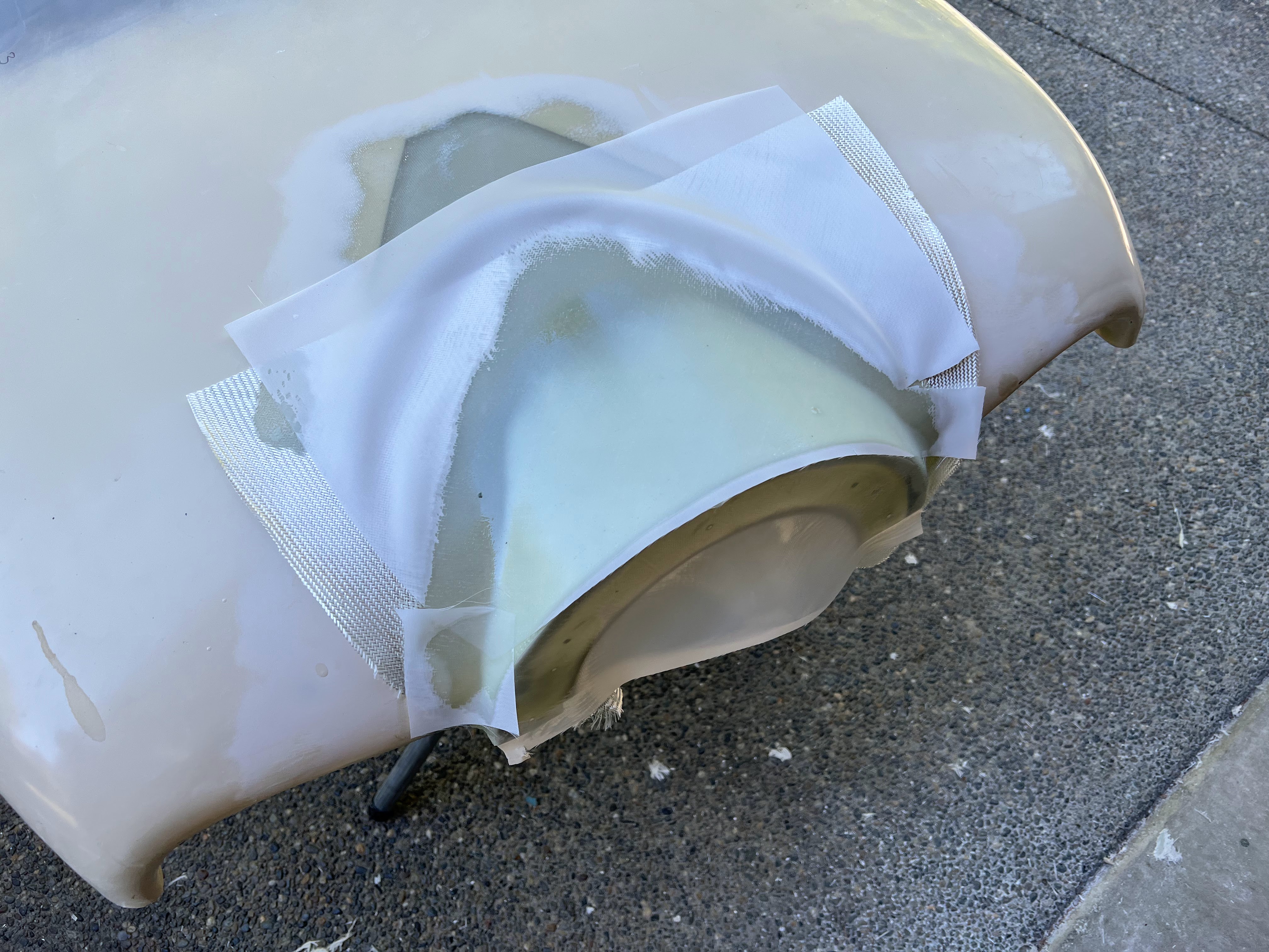


2nd layer applied after sanding.

This time I peel ply'ed everything.  After the first layer, you could really see the weave.  Hopefully the peel ply works.  I had to put it on it small strips because of the compound curves.

After removing the peel ply and cleaning up the edges, figured I would test fit everything again to make sure I am going in the right direction.


It all lines up pretty nicely.  Needs some finessing around the cowl split behind the spinner, but everything is lining up as intended.  That is a huge relief as I dont want to do this again


Just finished trimming the upper inlets after extending and re-profiling them.  Started by bonding in foam and glassing against it.  Sand the foam away, fill for profile (mixture of cabo and micro), sand, then 2 layers of glass on both the top and bottom, then sand again.
Now I have to do the bottoms.

The exit air ramp at the bottom rear of the cowl needs to be extended.  I've been thinking about how to do this for over 9 months.  The plan is to use aluminum to conform to the existing partial ramp, and just extend it in height and width.  With the extra large oil cooler and intercooler I need more exit area.

I've had the aluminum for weeks and have been staring at it.... well finally said just do it.

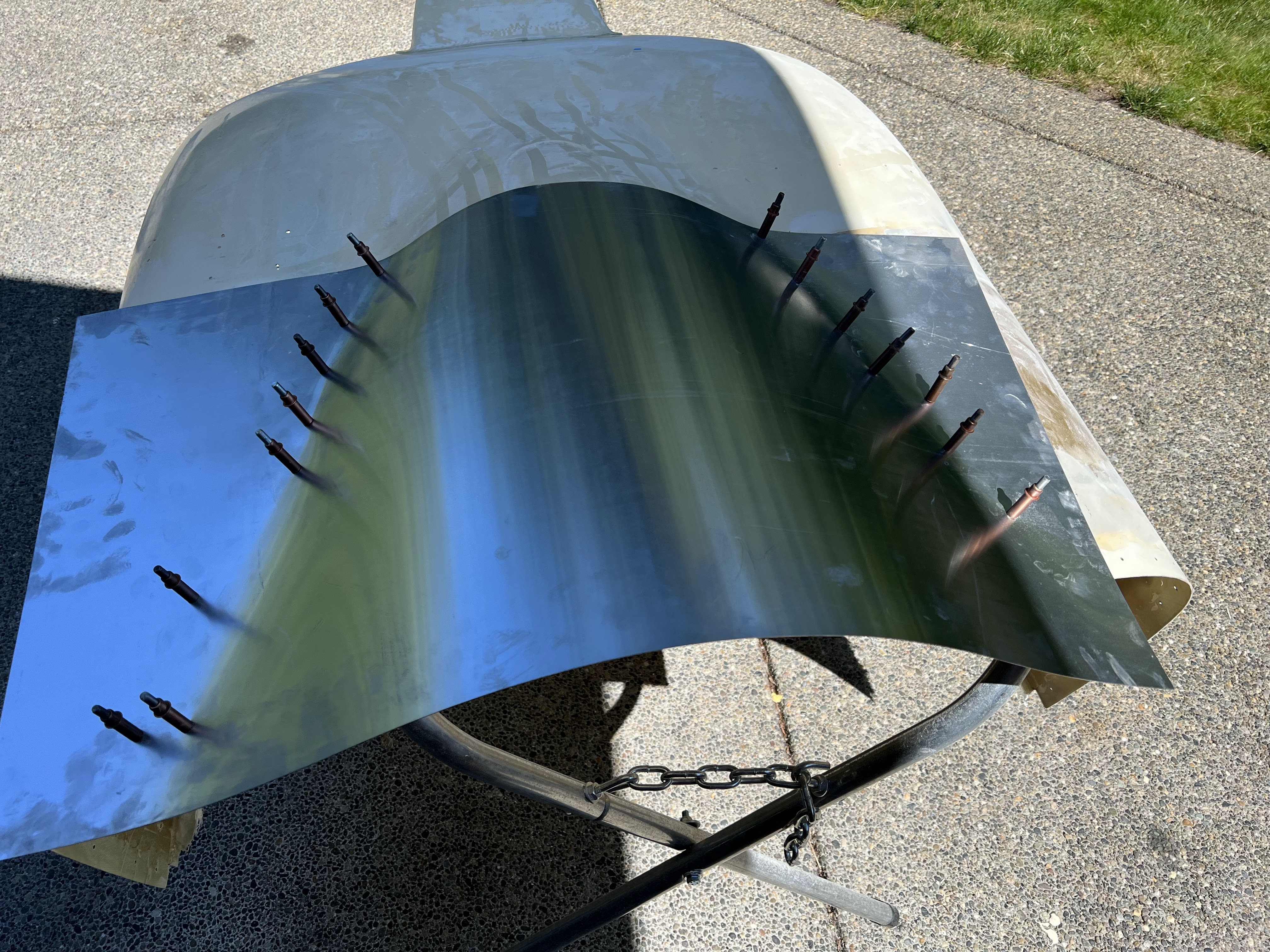
I started out by working one side... getting the curve right, and drilling / clecoing as I went.  I think it took all of 15 min tops.


Next was trimming back and sanding the cowl.  Debur a few holes, clean the mold/aluminum, mold release, re-cleco, and start mixing resin.


3 layers of cloth, 1 layer of peel ply.  Once this is cured, take the peel ply and mold off... then will grove/dish the seam on the outside and put 2 layers of glass on the outside seam, then fill to flush.  I will probably put a 4th layer on the entire outside.  That should be plenty strong.

I want to put a lip on the aft edge of the ramp... apparently this helps draw out air.  But I have not figured out how I am going to do that yet.


Took the mold of yesterday.  It definitely worked... however it is very big.  It is currently too long as well, which makes it look even bigger.  The good news there is plenty of room for the exhaust.

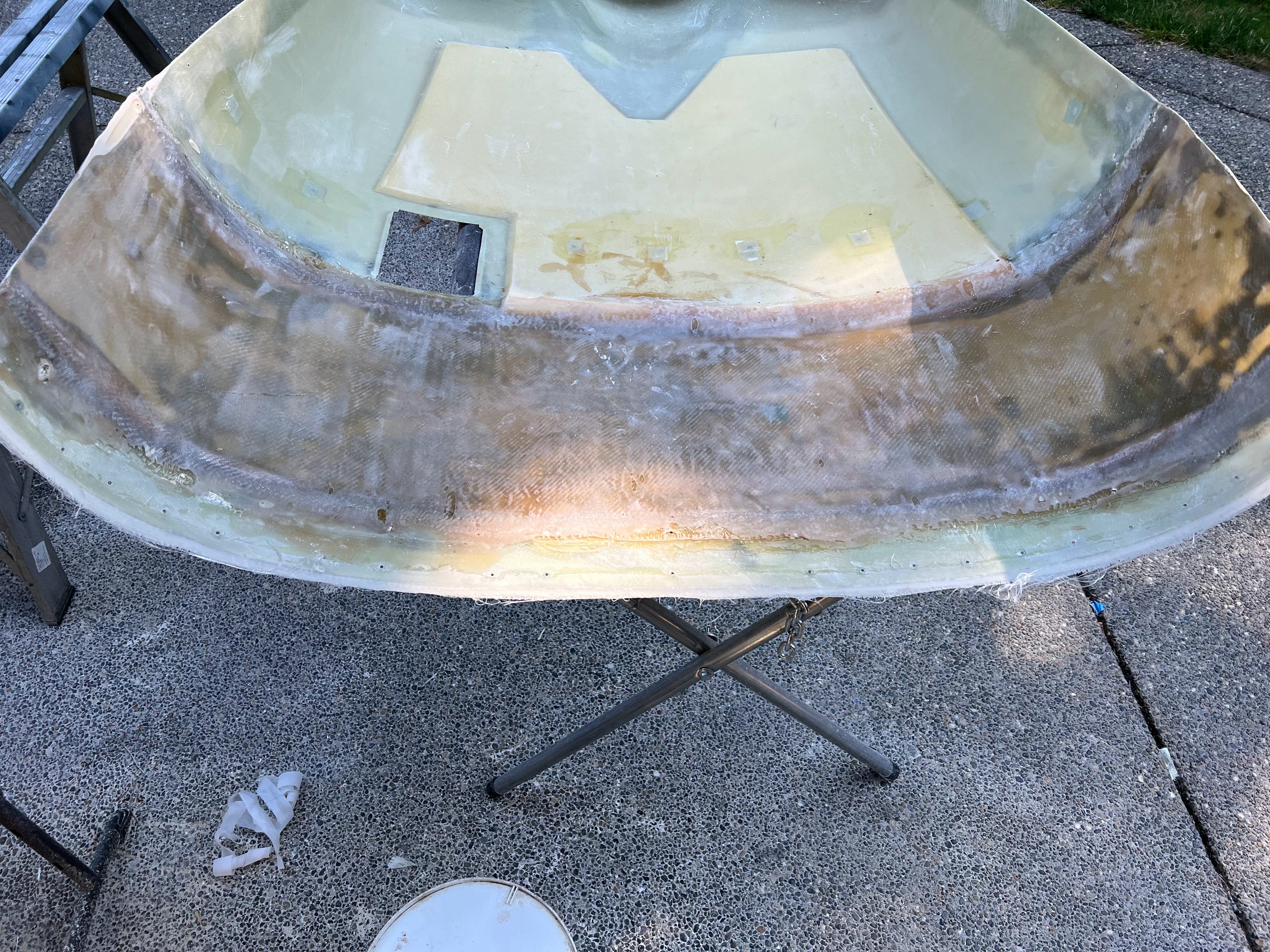
Got a lot done on the cowl in general.  Sanded the outside down in preparation for the 2 layers of glass to tie the outside of the exit air ramp extension - glass applied.  Started filling the slot for the nose gear.  Bonded in foam to fill the taxi light depressions, plus a layer of micro where the foam did not fill completely.  2 layers of glass on the outside of the oil cooler inlet.

Plus, I layed up 2 strips 44" long 4" wide of glass for my new cowl joggles.  When I finally cut the cowl sides down the size, most of the joggles will be gone and will need to be rebuilt.

Now it all just needs to dry, and then more sanding - YAY!


If the cowl wasnt ugly enough.... after lots of sanding, working on filling the gaps from the last layers of glass.


The light depressions have a layer of glass on them.  The oil cooler inlet has been faired.  The outlet ramp has been faired, and I started on the last of the 'oopses' from the lower cowl extension.  Tomorrow will be lots of sanding (again).

The top cowl needs some love.  For some reason (either erosion, or something moved or both) the top cowl does not line up with the fuselage goggle.  In some places its right on, and it one spot is almost 1/8th out (erosion), and it a few places its just a hair off.  

After consulting with Zach, I am going to extend the hole top edge of the cowl about 1/4", refit it, and them trim.

The mold is aluminum.  For the most part, I used the holes already in the cowl to temp mount it - but added a few more where the aluminum was not laying correctly.


I taped the the top (bottom in the pic) with packing tape to try and minimize the amount of resin that bleeds through.  Mold release on the aluminum, and cleaned everything.  One 5/8" layer of glass with peel ply on top.  Once this is cured with flip it over, give it a light sand and then another layer on top.
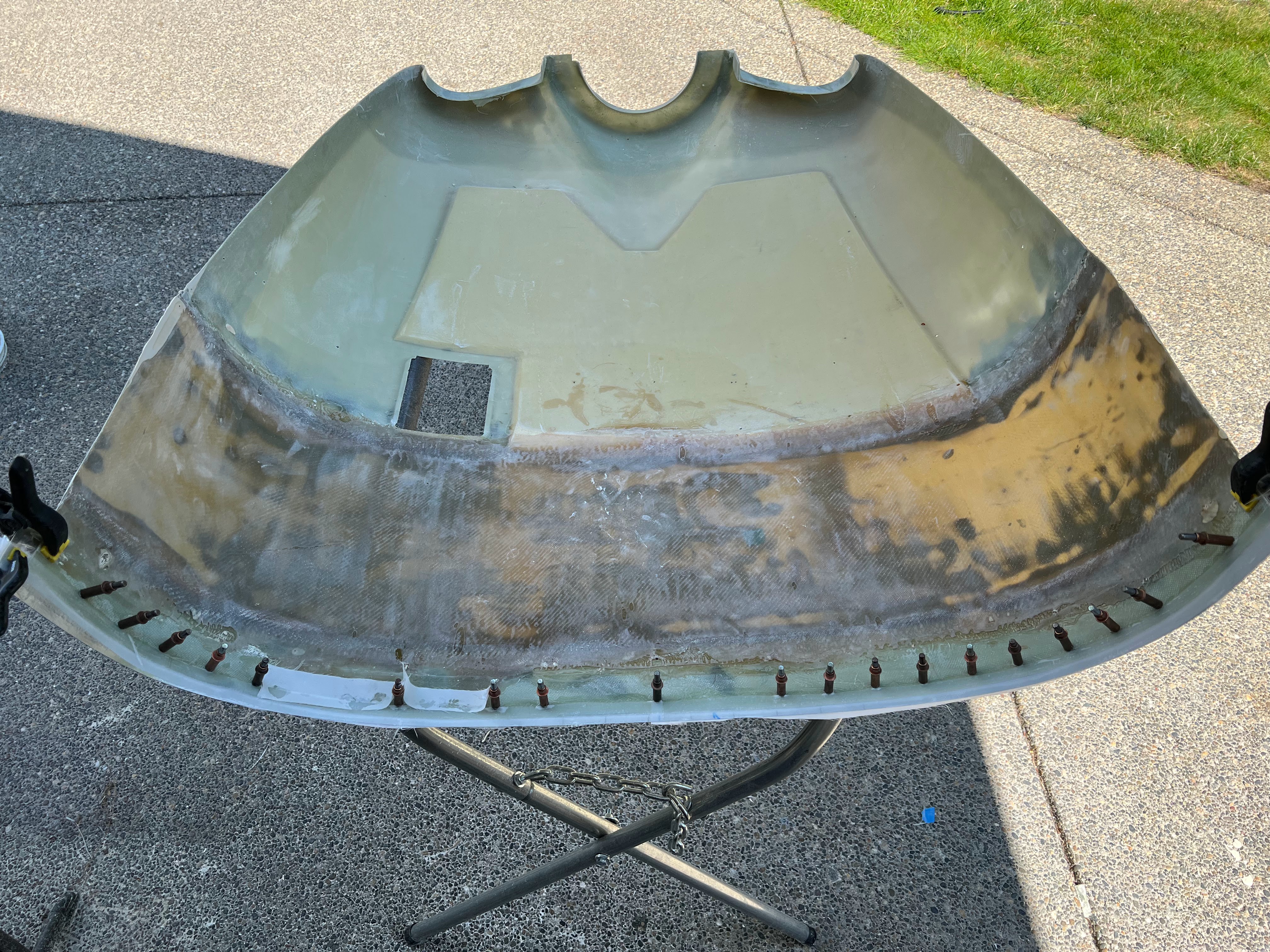

All gooped up.

Looks like it turned out OK.  I extended the edge for more than I needed.  Also started filling holes...


It sure looks ugly...

Test fitting after all that work... and marking the cut line
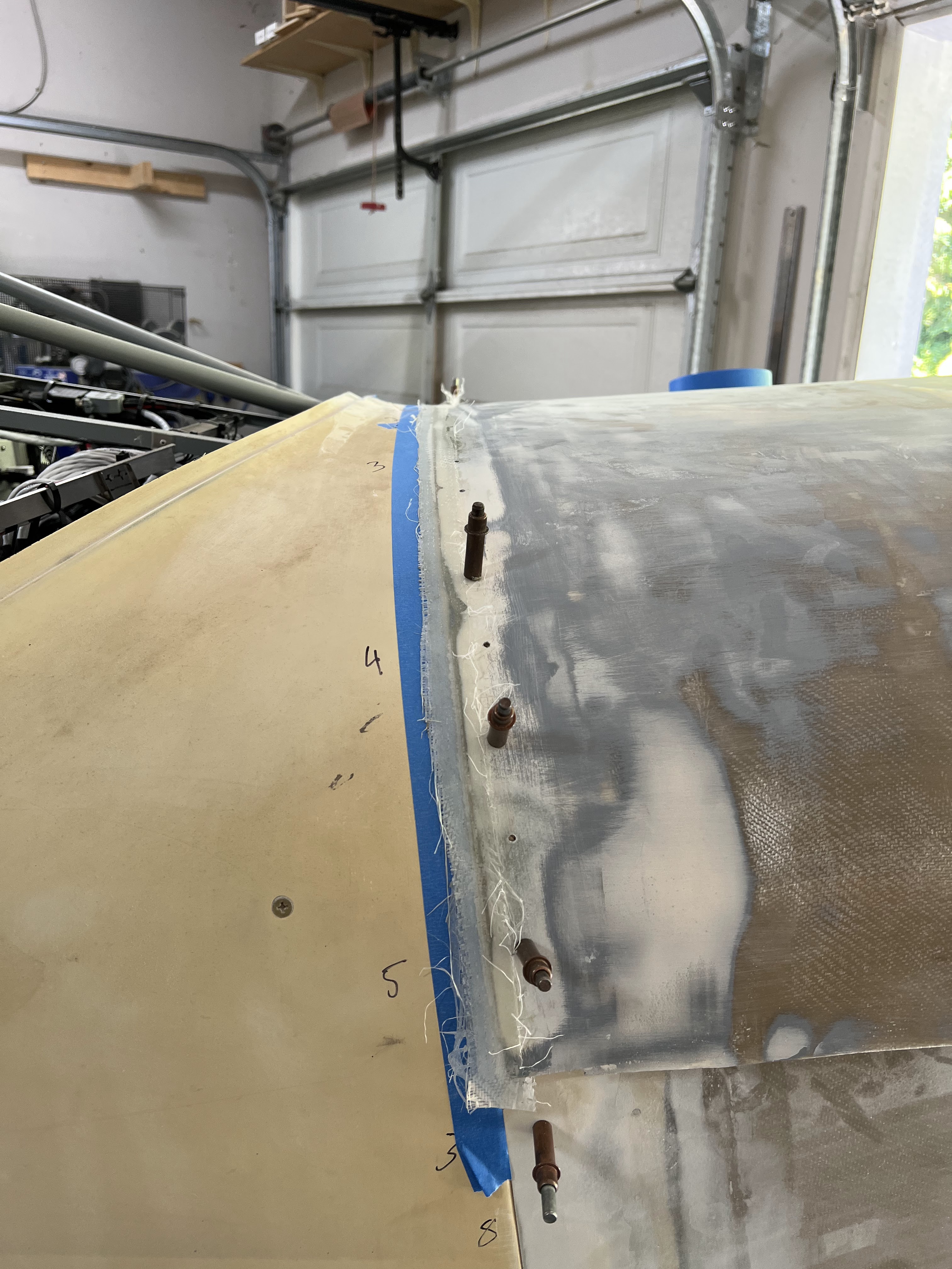


Came out not too bad...  Way better than it was

So ran into a problem.  When I cleco the cowl in place, it shifts slightly to port and its hitting something hard.  Finally realized its the slip ring hitting the inner ring of the cowl.

The opening in the cowl is 8" wide on the aft side (it tapers slightly with the curve of the flange).  The slip ring assembly is 8 3/8".  I am going to shoot for a 1/2" gap (I think that is safe), so the new inner flange will be 9 3/8".

The plan:

  • Make an MDF ring the fits into the space on the inside of the cowl with room to fit the slip ring with no interference plus 1/2" or so on each side.
  • Route the inside of the ring to ~1/4" radius.  Sand and finish the ring, wet sand to a nice finish
  • Cut out the existing flange, sand the freshly cut edge to a taper
  • Attach the cowl halves
  • Drill and cleco the ring in place
  • 1 or 2 layers of glass on the outside.  Probably 2, so I can sand one partially away
  • Remove ring.  2 layers of glass on the inside
  • Trim edges, cut slot between rings
  • Pray it worked.
The big benefit to this change is the brush bar for the prop / slipring no longer needs a notch in the cowl.  OK, minor benefit LOL.


Everything fits much better now.

Finally got up the nerve to do the big cut on the lower cowl to remove the excess material (due to the stretch and reprofiling).  


Now the joggle rebuilt begins...


New joggle strip cut and fit.  It's 3 layer of glass that was bonded up separately


Bonded in place using a mixture of resin, milled fibers, and a dash of cabosil.  Clecos were spaced every 1.5".  I put 2 additional layers of glass between the cowl and joggle in the extension, as it was noticeably thinner than the rest of the cowl.  All the squeeze out was cleaned up after everything was in place.  There was a lot of material to remove... I probably over did it a bit.  I put a lot of tape on the inside to catch the squeeze out, and then cleaned it up with a bit of acetone.  Once this is dry, going to add 2 more layers of glass on the inside to strengthen it up, overlapping the joggle onto the cowl.


Other side done.  Time to add more glass to the flange and create an overlap.

2 more layers of glass on the inside to bond the joggle flange in.


Somehow the cowl has shifted slighly.  I have pulled out my hold alignment jig that attaches to the crank.  Originally it fit inside the inner ring on the cowl, which is no longer there.  I aligned it by hand and drilled new holes for the aluminum.  I have successfully got it back into alignment with the spinner.

Going to work from the front to the back and align the cowl and drill the holes for fasteners.

Going with 6.4" spacing across the 39" from the aft of the cowl up to the last 5" where it curves to much for skybolt fasteners.

Also, before doing this I sealed up all the holes in the aft of the top cowl.  1 layer of glass on the bottom, filler on top.

Once everything is aligned, I put 2 new holes in the top cowl, straight through the goggle and firewall stainless.  Then I used a ratchet strap to pull everything relatively tight.


Fastener pilot holes drilled on the cowl sides and top.


Test fit of the hub and spinner.  It all lines up like it should.

Now I have to deal with the bottom, including cleaning up the exit air ramp.

Small problem encountered with the top of the cowl at the seams for the extension.  As the cowl is thicker at that location, it wants to bend less - so is not sitting nicely in the joggle.  You can push it in with your finger.  The plan will be to relocate the fasters to these 2 areas on each side to get it to suck in.  That will mean respacing all the fasteners - but its worth it if it works.

Working on the top/bottom cowling seem at the front.


Same picture as above, but after lots of sanding and filling.  All of the 'real' faster locations have been drilled and the cowl is now rock solid.  Because the cowl has been on and off so many times many of the holes had started to oblong and the fit was getting sloppy.  Its all good now.

So it's time to prime.  I could keep chasing defects, but my current theory is a high build primer will eliminate the small stuff, and then I can focus on the big stuff.

Initial impressions are really good.  I am using a SEM rapid primer / filler procured from the local auto supply shop (Lordco).


Most of the minor imperfections are gone - which is great news.

Before sanding
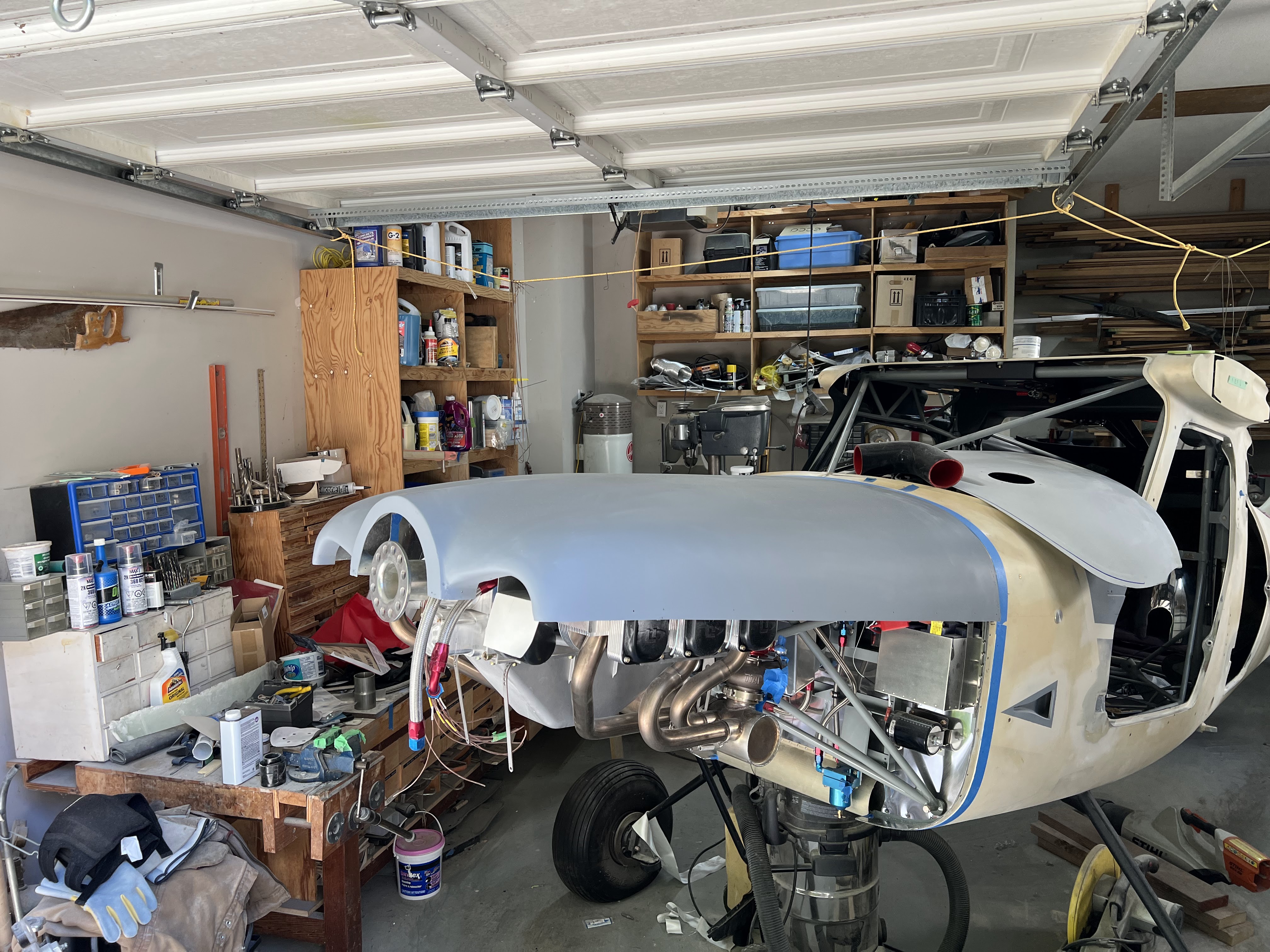

There is a fair bit of stuff that needs addressing, mainly around the ends (cowl trailing edge, and the inlets where they have been enlarged).

After initial sanding.


I did the cowls in separate stages.  Started with the top because it was 'better' (less defects), and I had not final sanded the bottom cowl yet.  After sanding, I went after all the little issues.


As for filling... up until the primer stage I used West Systems Epoxy with their 410 Microlite Fairing Filler.  I can mix this up in larger quantities, and depending on where I am filling I can add Cabosil, Milled Fiber and/or Filler and I can adjust the quantities to get the necessary consistency / strength.  Now that I am at the priming stage and going after the little stuff, I am switching to Total Boat / Total Fair fairing compound.  Total Boat works really well for the fine details.


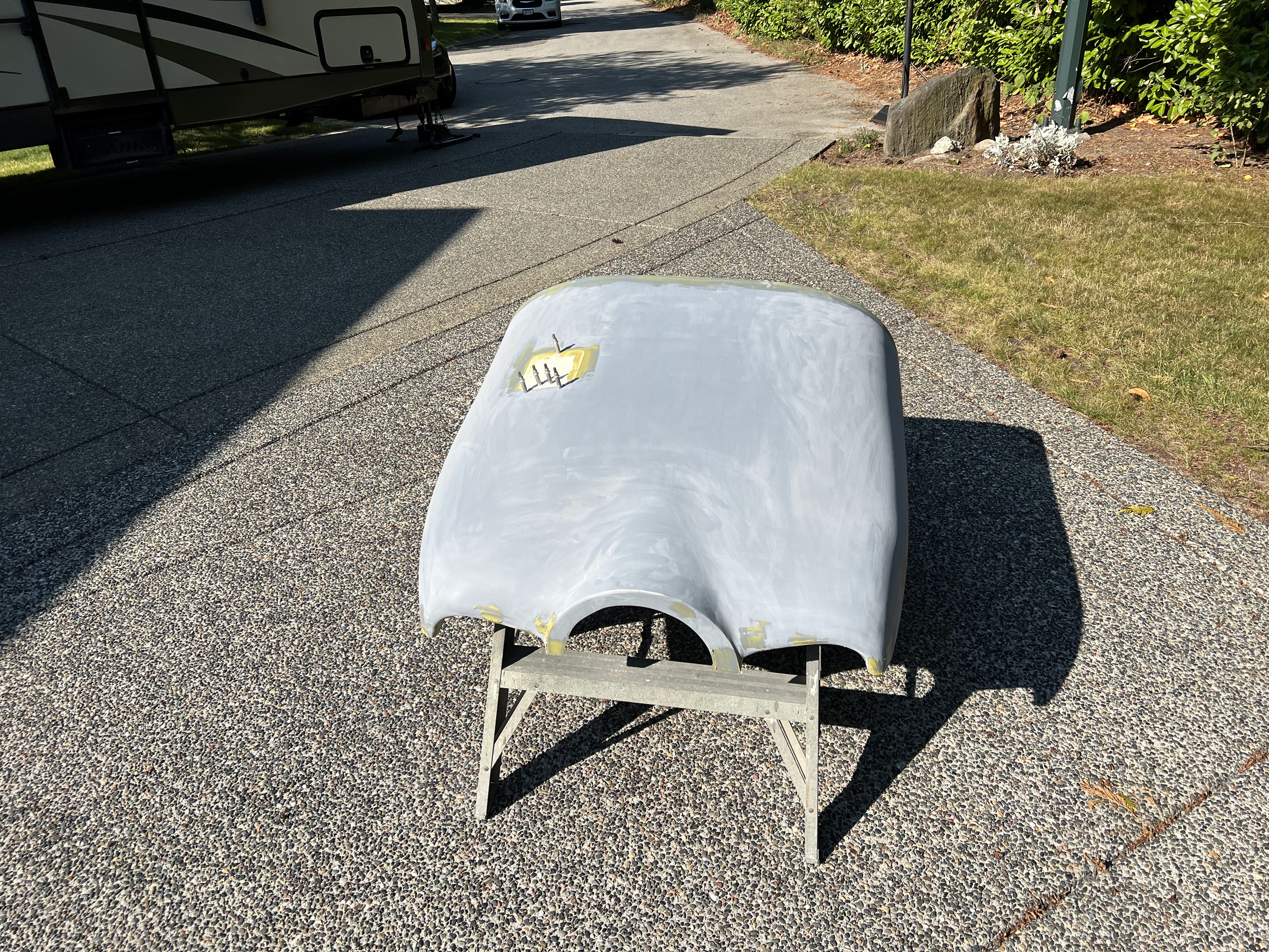
The upper cowl has been primed, sanded and filled and is drying - so onto the lower cowl.  Unfortunately the lower cowl has been butchered, extended, reworked, stuff added etc.  It needs some love.  I am very confident in its strength... now I have to make it look beautiful.

Prior to priming...


I am using my 'shed' for the RV.  Its covered and somewhat sheltered from the wind.  Prior to doing anything, I water down the area where I will be working with water to keep the dust down.  I usually start on the top surfaces, and then flip it over and work on the bottom.


Doesn't look to bad in the picture, but in reality it looks like an obese person wearing yoga pants (that shouldn't).  Lots of defects.  But man, it sure is nice to see everything one consistent colour and not a hodge-podge of crap.  Plus, the SEM Rapid Primer Filler dries really fast, which is awesome.

Test fit after 2nd run of primer / filler.


It actually looks not too bad.  There are a lot of little things to chase.  The seams between the bottom and top halves need work, and there are some little pinholes.  But, basically its together.  Everything lines up.

Here is the progression over a year....


I stopped working on the cowl in approximately October 2022 when the weather cooled, and started up again in June 2023.

So today has been all about chasing gaps between the upper and lower cowl.  They were not consistent.  When I marked the cut line, I used a long straight edge and clamped it to the cowl.  However, the cowl curves, so the cut line had a curve on the forward end.  Its not huge, but you have to follow it.  I made the decision to do small portions of the gap individually... which means lots of top cowl on and off.  More work and longer, but it seems to be paying off.  Working to get to a consistent ~1/16th gap from the back to the front.  Sure would have been easier to just hold my nose and buy a Lycoming... especially with all of the UL issues of late.

Started installing fasteners along the upper cowl aft edge.  Its coming along...


Going to leave the rest of the cowl for now and focus on windows, oil cooler, intercooler, etc.  The cowl is 90%+ complete thankfully.


Wednesday, 30 August 2023

Update - August 2023

I haven't posted much lately, but that is because things are not finished and ready to post.  I have actually been making pretty good progress.

The cowl has been a lot more work then I planned on, but it is getting close.  More sanding and filling, and then I can start priming it.  I have all the fasteners and have been playing with them on some scrap fiberglass.

The engine plenum is ready for fasteners - but i am waiting to figure out the intercooler plumbing from the front of the cowl to the back.

Waiting on exhaust parts.  I bought some amazon 304 stainless, and did not like the look of it so I am getting bends from the factory in Europe.  Hopefully I will have pricing and shipping details soon.

The intercooler is completely mounted, and the intercooler plenum is build, finished and riveted.

I bought an air fuel ratio monitor.  Need to weld in the bung, which i am going to do when welding the exhaust.

All the firewall forward fuel lines are done.

Played around with wrap on the control surfaces.  Pretty sure I am going to paint.

Oil cooler is done, except I need to make 1 new bracket.  All the oil lines are done and the oil filter adapter is mounted.

The oil filler door is on, but needs some tweaking.

The glareshield is almost ready for upholstery.

I have the crimper for the plug leads, but havent started that yet.

1 window is in, and in the process of fitting 2 more of 7 total.

So lots of progress, and lots to go.  BUT ITS PROGRESS!

Tuesday, 29 August 2023

Windows - Part I

Well, I am finally thinking about windows.

Part 1 in Zach's video series is located here.  I watched these years ago - just finished watching them again, and figured I would take notes.  Where Zach jumps ahead or goes backwards, I have updated the sequence to be linear.


Materials Needed

  • ~12 wet erase markers
  • Fresh razor blades
  • Home depot style paint stir sticks
  • ~20 3/32 wing nut clecos
  • 2" 3M 2090 tape
  • 1/4" masking tape (not fine line tape)
  • Silpruf - check expiry date
  • Permatex RTV silicone gasket making material - Ultra Grey
Steps - this is a culmination of all the videos.

  1. 3 to 4 days in advance, lay down some lines silpruf on a scrap piece of aluminum.  These will be used to create standoffs for the plexiglass against the joggle.
  2. Pull back ~2" of the film on the window all around the edge, both top and bottom.
  3. Lay the window into the joggle and mark where it needs to be trimmed to fit inside the joggle.  Trim window to expose enough of the joggle so a line 3/16 from the joggle can be made on the window using a wet erase marker
  4. Sand joggle and return.  Fix any defects in primer or gel coat
  5. Mark the 3/16 line from the joggle on the window
  6. Trim up to the line - but not past the line.  Will probably take 2 passes.
  7. Check fit of window
  8. Drill #40 holes for wing nut clecos and install.  Use pieces of Home Depot stir stick with 3/32 hole to act as bridges between the window and fuselage.
  9. Mark INSIDE of window at joggle - this will be used to tape the inside of the window
  10. Mark the joggle on the OUTSIDE of the window.  This will be used to tape the airframe and stop silpruf contaminating the surface to be painted
  11. Tape the INSIDE of window in 3 steps
    1. Blue 1" 3M 2090 tape ~3/16 from pen line
    2. 1/4" masking tape up to but not covering the tape line.  Mark as tape #2
    3. Remove black line using moist paper towel
    4. Use another piece of 1/4" masking tape to overlap tape #2 by ~1/16".  The purpose of this tape is to remove the initial silpruf layer to get a clean edge.  Mark as tape #1
  12. Sand outside edge of window to either 100 or 120 grit, more if desired using a sanding block
    1. Ensure you get any nicks out of the edge
  13. Sand by hand with a piece of 120 grit paper in your hand to put a soft 1/16" edge on the edge of the window
  14. Tape the OUTSIDE of the window
    1. 2" tape around the outside of the window, overlapping the window slightly
    2. Using a razor blade on an angle, cut the excess of the tape off.
  15. Sand the inside of the window that is not taped with 80 grit using your finger as a guide, but do not sand the tape
  16. Wipe the inside of the window with a fresh dry paper towel to remove any dust
  17. Add a bead of silpruf to create a boundary layer on the exposed window edge.  Smooth with your finger.  Start with a small amount and add if needed.  Create an opaque layer that you cannot see through
    1. Only put the boundary layer on if you are going to install the window within 12 to 24 hours
  18. Remove tape #1 from the inside of the window before the silpruf dries
  19. Set aside and let cure 12 to 24 hours
  20. Taping the airplane - paint later option
    1. Using the blue 3M 2" tape, tape the outside of the joggle up to the line inside of the joggle.  Use small pieces around the corners.  Press the tape into the corner of the joggle using the cap of the pen.
    2. Mark the tape on the outside of the joggle indicating where the holes for the clecos are located.
  21. Standoff placement
    1. Using the Permatex ultra grey silicon, bond in the standoffs wherever needed - but at least at every cleco.  Put the standoff at the inside of the hole
  22. Back tape the inside of the fuselage and trim with a razor blade
    1. Cut flush with side of joggle
  23. Once dry (from step 19), take a razor blade and scrape the edge of the window to remove any dried silpruf.  Do not roll it off with your finger as it may come off the bottom cosmetic layer of the silpruf
  24. Trim the dried standoffs in a trial and error manor to get the window to sit flush with the joggle.  If in doubt, leave slightly proud as it will compress with the cleco
  25. Silprufing the window
    1. Check the tape on the inside of the window to ensure it has not rolled up.
    2. Redrill the cleco holes to puncture the tape on the inside of the fuselage
    3. Clean the inside of the joggle and window with a dry paper towel
    4. Dab silpruf along the tape line in the inside of the window.  Rub it in between the cured silpruf and the tape with your finger.
    5. Fill the joggle up with silpruf.  Overglue rather than underglue.  
    6. Depending on the height of the standoff, vary this bead thickness - between 1/8 and 3/16
    7. Working time is ~45 minutes
    8. Lay the window in place 
    9. Push the window down where the cleco is going to go.  Clean the area around the cleco using a 1" piece of a spreader
    10. Insert the wing nut cleco and tighten until it does not move.  Do not overnighten.  The goal is to get the window flush with the joggle.
    11. Repeat steps 9 and 10 until complete
    12. Clean remaining silpruf in seam between window and joggle.  Drag from the outside to the inside pushing silpruf towards the window edge.
    13. Start pulling the tape carefully up to a cleco.  Remove and clean the cleco, and flip the wood bridge over and reinstall.  Repeat for all remaining clecos.
  26. Clean the inside of the fuselage
    1. Using a small piece of scraper, gently drag the silpruf between the edge of the window and the joggle.  The goal is to smooth it out
    2. The goal is to backfill the gap between the joggle and window with silpruf, and remove any large chunks of squeezeout.
    3. Pull tape #2
    4. Clean up cage tubes if required.
    5. Leave clecos in for minimum 2 days for all windows except front window.  4 days for front window
Starting on the pilots side roof window.

Rough cut to fit in joggle.


I am using my air powered orbital sander with a 6" disk.  Not quite as aggressive as what Zach uses in the video, but I am just fine with that.


Rough cut #2


After 3 trims, I am happy.  Proceeded to drill and cleco.


Inside tapped off with 1/4" masking tape marked.


Both sides of window masked.  Inside and outside of fuselage masked.


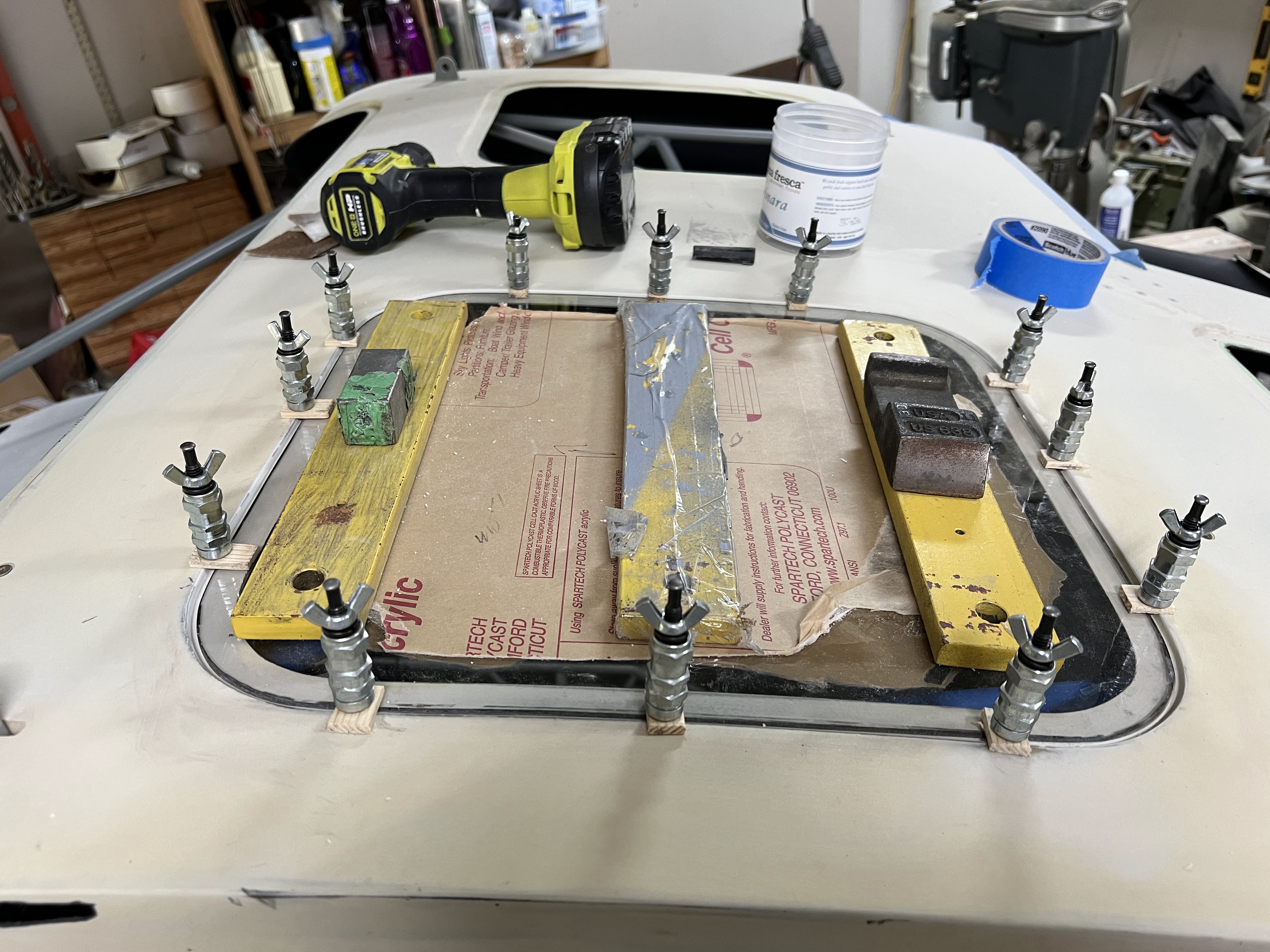
Standoffs glued with RTV.  Note - I also taped off the inside of the cage from the top.  Hopefully this is not a bad idea (in terms of removal down the line).  Per the instructions, I should have applied the cosmetic layer on the bottom of the window already... however I am tied up for a few days and wont have a chance to put the window in, so going slightly out of sequence.  Will get the standoffs cut, and then go back and do the cosmetic layer.

Everything fit and silpruf'ed in place.


I used way to many clecos.  At first I didnt put them in the corners, but had 3 along each side.  After going back and watching the videos again, I realized that the corners were the most important so I added them.

I pulled the tape back in a couple areas to see how the cosmetic layer looked - its OK.  I wish it was a bit crisper but I am fussy.  Only 6 more to go (sigh).

The above process worked quite well all in all, especially for a first attempt.  Hoping they get better from here.


Friday, 16 June 2023

UL520T Crankshaft Failure / Investigation

In early May 2023, there was an accident with a Rans S12 powered by a UL520T.  Preliminary accident report available here.

As stated in the prelim accident report, the engine had been experiencing high CHT temperatures on one side of the engine and the builder had increased the size of the oil cooler and was working on overall cowling / cooling issues.  No reports of high oil temperatures are present in the prelim findings.

I have talked to the US Distributor and other builders about this accident - which is very concerning.  A crankshaft failure is not something to be taken lightly.

I am not going to get into relaying what I have heard about the circumstances around this incident - although there appears to be extenuating circumstances.  The crank failure was most likely a result, and not necessarily the cause.  But the nature of what started the failure chain are not yet known.

Bottom line:  I am going to wait for the 'final' report before making any decisions.  The week of June 19th, 2023 the NTSB is going to perform an detailed analysis of the crank and case with the assistance of the US Distributor.  The factory is fully cooperating with the investigation.

This is the first crankshaft failure of any UL engine.

More questions than answers at this point.

I am going to continue forward on the build, but spend as little money as possible on the engine side of the install just in case I have to abandon it.  I truly hope that is not the case, but a definite possibility.  Flying behind an engine you do not trust is not a happy feeling.


Saturday, 3 June 2023

UL ECU Update and Issues

 Up until now, all of my interactions with UL Power have been excellent.  Super responsive (considering time zones), and reasonable.

UL changed a number of ECU parameters last year, and mine had to go back to the factory in Belgium for a software update.  So I packed it up in March, and UL arranged for everything else.

In May, I reinstalled the ECU.  Everything appeared fine... but the CANBUS feed from the ECU was now on lane B and not lane A.  I also thought there were a bunch of sensor failures (but that turned out to NOT be the case).

UL claimed that the CANBUS lane A / B decision is made via the cable.  After some sleuthing on the diagrams I found the pins and checked - no jumper.  UL then stated they were going to test with my version of hardware - and they found the issue.

The explanation given:  I have board version 63, and they are now on 64.  They added additional input ports, which shifted the CANBUS lane A / B jumper.  

The label on the ECU says

HW ver 1-63

SW ver 07-022

Based on my experience in over 30 years of dealing with hardware and software issues, there are more issues than what I am being told.  They GUARANTEE everything is fine, and no need to update the ECU software.

I do not agree.

I am trying to stay positive on UL as 1 bad experience should not taint all of the good things they do and have done.  But this has definitely left a bad taste with me.

90% done, 90% to go - be done on Tuesday

 It's a long list of what is left, but its getting shorter (last updated Sun, June 11).  This is to keep me focused and motivated.

Things to do at home
  1. Complete intercooler air inlets, and finish brackets
  2. Complete air cooler brackets, open hole in cowl, make mold, finish cowl
  3. Modify cowl for larger spinner
  4. Finish cylinder air inlets
  5. Exhaust - from UL stubs 
  6. Finish air outlet on cowl (exit air ramp)
  7. Plenum tops
  8. Plug wires, CHT and EGT
  9. All windows
  10. Brakes - from park brake valve to calipers
  11. Finish pitot lines
  12. Air intake / filter / alternate air source
  13. Cabin heat plumbing - firewall side
  14. Put doors on
  15. Finish mounting hardware for rudder and cables
  16. Fuel plumbing from gascolator to engine. Return line from engine to firewall
  17. Gear leg fairings
  18. Wing to fuselage wiring connector (fuselage side done)
  19. Install interior
  20. Glareshield upholstery
  21. Tighten up tailwheel bolts
Things to do at airport (final assembly)

  1. Strut to wing and strut to fuselage fairings
  2. Hang wings
  3. Finish hatches and flap fairings
  4. Wing tips
  5. Lights
  6. Wing to fuselage wiring connector (fuselage side done)
  7. Brake fluid / bleed brakes
  8. Wing mounted antennas / coax cabling
  9. Paint

I will probably keep this list updated as I think of more things and scratch some off.

Wednesday, 31 May 2023

Throttle

The throttle for UL engines is a bit different than standard aviation 'stuff'.

The throttle body is on the top of the engine.  There is a spring on the throttle body that holds it OPEN.  The standard UL installation is essentially a bike type cable that draws the throttle closed.

I am going with a standard aviation type throttle.  Specifically a McFarlane locking vernier assist type.

The dimensions are not standard.


The firewall penetration is complete, and I had a 48" throttle I could use for mock up.  A fellow builder went through this a couple weeks before I did, and sent me his design and I used that as my starting point.

Ordered.  Should be less than 2 weeks to fabricate and ship.

Will need to build a custom bracket to seize the throttle end, using the rear engine hoist mount.

Almost 2 months later... we have been to California and back on vacation, and work has been nuts.  Have not had much time to work on the project.  But the throttle has turned into a comedy of errors.

  • I had the throttle shipped to a package service in Blaine, WA.  I do this a lot... saves on shipping and brokerage fees.
  • The plan was to pick it up on the way back from California.  We would have been down long enough that I would not pay tax on the throttle (its not huge, but every bit saved adds up).
  • The package service has 24 hour lockers.  You request the locker by 2PM, the packages get loaded, and then you can pick it up whenever you want.  This service costs $1 (on top of the $3 per package).  Very convenient.
  • While we were in California, the package service had a fire in their locker facility, which moved into their warehouse.  Lockers are destroyed (and anything in the lockers was not recoverable).  Super sad for the business.  They are such nice people.
  • Bottom line... I couldnt pick up my throttle on the way home.  Went down a week later to grab it (and my intercooler).
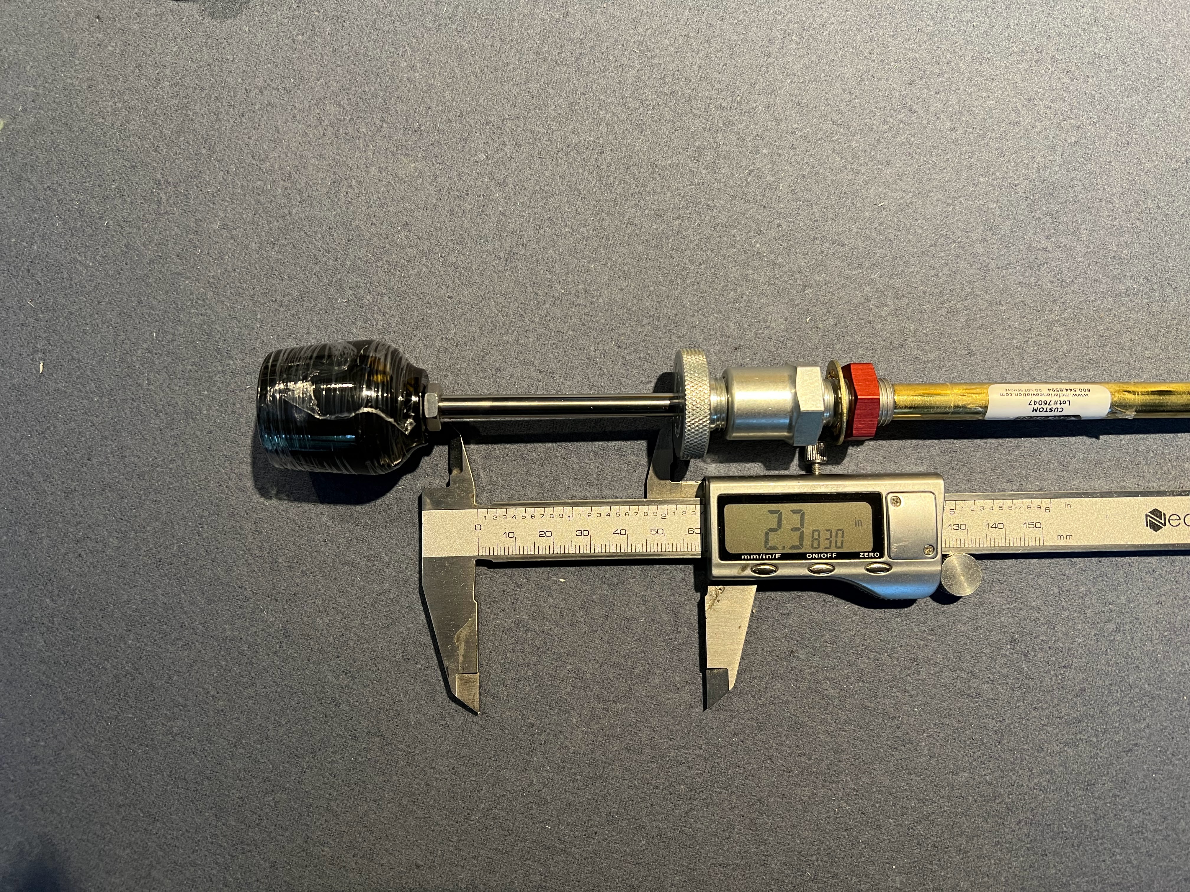
  • I get the throttle home, and start test fitting it.  The UL engine needs just shy of 2.5" of throttle travel.  My custom throttle has 2.38".

  • Well thats not going to work... I email pictures and call McFarlane.  According the the service rep I dealt with (who was super helpful), it was made this way on purpose to "maximize the overlap at the throttle end", based upon my drawing.  Well, the throttle calls out the minimum required travel / throw of 2.5".  Bottom line:  redesigned the throttle to get 2.5" of travel.

  • Above is old / new.
  • New throttle is ordered, and should have it within a couple weeks.
New throttle has arrived, and boy is she a beauty!  I messed up when I ordered originally and used the non vernier form.  McFarlane was very accommodating and built the new one as a vernier control.  Also, they sent the incorrect tool last time, and sent the new one at no charge.  The service was outstanding - zero complaints.

The vernier control version of the throttle is different.  The locking mechanism ships separately and needs to be installed.  There is a big note on the locking mechanism to NOT remove the temporary shipping shaft without the throttle shaft directly following it.  Of course I did, and all the roll pins came out.  Luckily they have a video on how to put it back together... disaster averted!

The nice part about the vernier control is you can mount it from the rear.  Doesnt matter now, but that may come in handy at some point in the future.

Nex challenge is the mounting bracket on the engine.  The stock UL bracket is for a bike style cable and sleeve.  Zenith has a bracket that mounts to the engine lift point location.  I am going to something similar.

First step is to make the plate that bolts on to the lift point.


I used a shape finder to get the curve around the starter.  The throttle mount point has to be about 3" back from the plate, and on a bit of and angle.  I made a template out of paper first, then aluminum to find the center of the holes, and then transferred that onto .063 4130 steel.  I want the plate as large as possible.

I am worried about the stresses on this bracket and vibration.  The location of the mounting holes is not ideal.  I put a bend in the left hand side of the bracket, and am going to add a small arm that goes over the top of the aluminum mount for some added rigidity.

The bracket is all tacked together.  Test fit.

Throttle fully closed.


Fully open.


Seems to do the job well.  Going to add a gusset to strengthen the arm.


Gusset added and everything tig welded.  Fits well and appears very strong.  No flex at all.

The bracket needs to filing and priming / painting - but will do that when I do the next batch of parts.