Search This Blog

Wednesday, 30 August 2023

Update - August 2023

I haven't posted much lately, but that is because things are not finished and ready to post.  I have actually been making pretty good progress.

The cowl has been a lot more work then I planned on, but it is getting close.  More sanding and filling, and then I can start priming it.  I have all the fasteners and have been playing with them on some scrap fiberglass.

The engine plenum is ready for fasteners - but i am waiting to figure out the intercooler plumbing from the front of the cowl to the back.

Waiting on exhaust parts.  I bought some amazon 304 stainless, and did not like the look of it so I am getting bends from the factory in Europe.  Hopefully I will have pricing and shipping details soon.

The intercooler is completely mounted, and the intercooler plenum is build, finished and riveted.

I bought an air fuel ratio monitor.  Need to weld in the bung, which i am going to do when welding the exhaust.

All the firewall forward fuel lines are done.

Played around with wrap on the control surfaces.  Pretty sure I am going to paint.

Oil cooler is done, except I need to make 1 new bracket.  All the oil lines are done and the oil filter adapter is mounted.

The oil filler door is on, but needs some tweaking.

The glareshield is almost ready for upholstery.

I have the crimper for the plug leads, but havent started that yet.

1 window is in, and in the process of fitting 2 more of 7 total.

So lots of progress, and lots to go.  BUT ITS PROGRESS!

Tuesday, 29 August 2023

Windows - Part I

Well, I am finally thinking about windows.

Part 1 in Zach's video series is located here.  I watched these years ago - just finished watching them again, and figured I would take notes.  Where Zach jumps ahead or goes backwards, I have updated the sequence to be linear.


Materials Needed

  • ~12 wet erase markers
  • Fresh razor blades
  • Home depot style paint stir sticks
  • ~20 3/32 wing nut clecos
  • 2" 3M 2090 tape
  • 1/4" masking tape (not fine line tape)
  • Silpruf - check expiry date
  • Permatex RTV silicone gasket making material - Ultra Grey
Steps - this is a culmination of all the videos.

  1. 3 to 4 days in advance, lay down some lines silpruf on a scrap piece of aluminum.  These will be used to create standoffs for the plexiglass against the joggle.
  2. Pull back ~2" of the film on the window all around the edge, both top and bottom.
  3. Lay the window into the joggle and mark where it needs to be trimmed to fit inside the joggle.  Trim window to expose enough of the joggle so a line 3/16 from the joggle can be made on the window using a wet erase marker
  4. Sand joggle and return.  Fix any defects in primer or gel coat
  5. Mark the 3/16 line from the joggle on the window
  6. Trim up to the line - but not past the line.  Will probably take 2 passes.
  7. Check fit of window
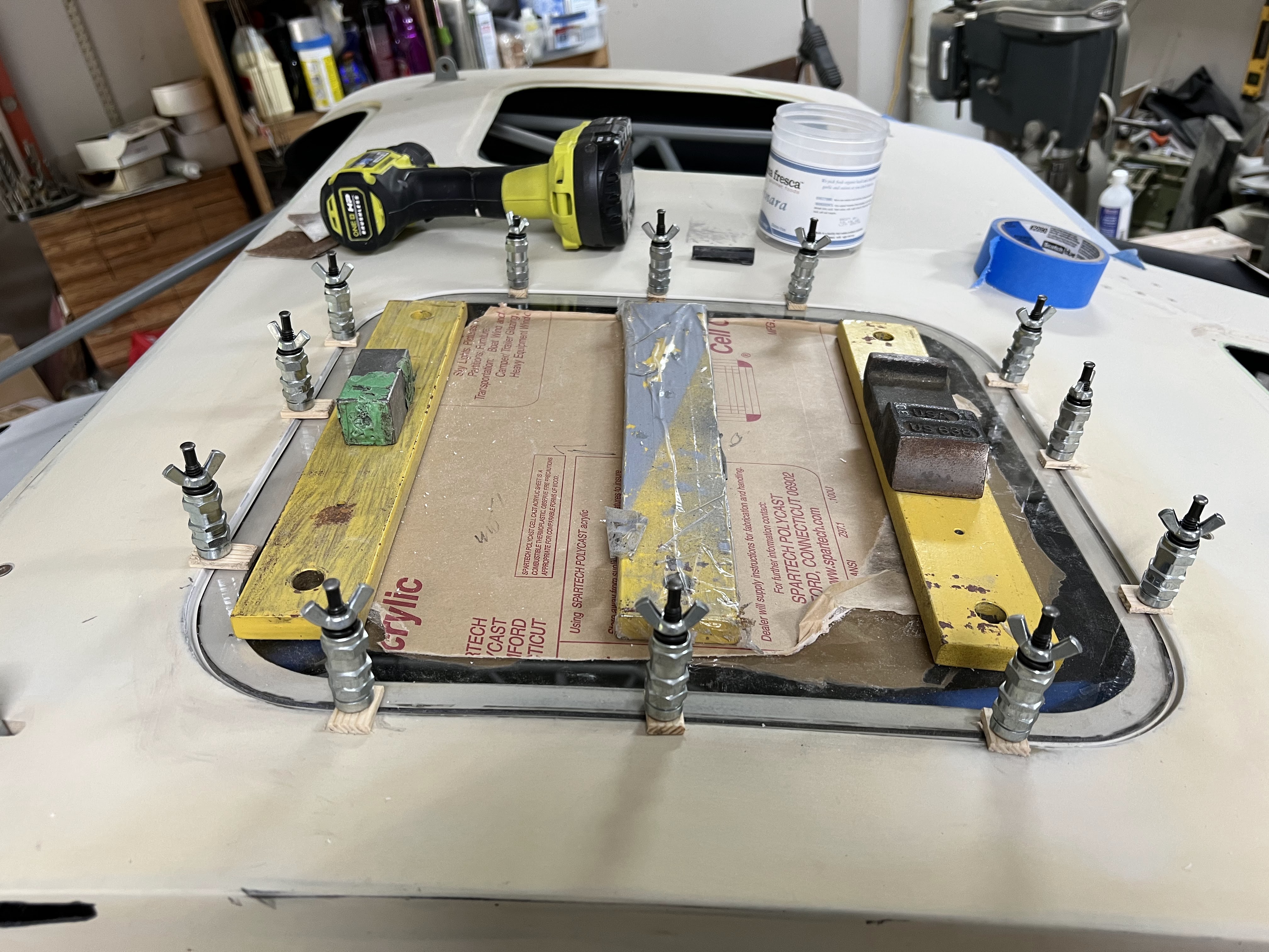
  8. Drill #40 holes for wing nut clecos and install.  Use pieces of Home Depot stir stick with 3/32 hole to act as bridges between the window and fuselage.
  9. Mark INSIDE of window at joggle - this will be used to tape the inside of the window
  10. Mark the joggle on the OUTSIDE of the window.  This will be used to tape the airframe and stop silpruf contaminating the surface to be painted
  11. Tape the INSIDE of window in 3 steps
    1. Blue 1" 3M 2090 tape ~3/16 from pen line
    2. 1/4" masking tape up to but not covering the tape line.  Mark as tape #2
    3. Remove black line using moist paper towel
    4. Use another piece of 1/4" masking tape to overlap tape #2 by ~1/16".  The purpose of this tape is to remove the initial silpruf layer to get a clean edge.  Mark as tape #1
  12. Sand outside edge of window to either 100 or 120 grit, more if desired using a sanding block
    1. Ensure you get any nicks out of the edge
  13. Sand by hand with a piece of 120 grit paper in your hand to put a soft 1/16" edge on the edge of the window
  14. Tape the OUTSIDE of the window
    1. 2" tape around the outside of the window, overlapping the window slightly
    2. Using a razor blade on an angle, cut the excess of the tape off.
  15. Sand the inside of the window that is not taped with 80 grit using your finger as a guide, but do not sand the tape
  16. Wipe the inside of the window with a fresh dry paper towel to remove any dust
  17. Add a bead of silpruf to create a boundary layer on the exposed window edge.  Smooth with your finger.  Start with a small amount and add if needed.  Create an opaque layer that you cannot see through
    1. Only put the boundary layer on if you are going to install the window within 12 to 24 hours
  18. Remove tape #1 from the inside of the window before the silpruf dries
  19. Set aside and let cure 12 to 24 hours
  20. Taping the airplane - paint later option
    1. Using the blue 3M 2" tape, tape the outside of the joggle up to the line inside of the joggle.  Use small pieces around the corners.  Press the tape into the corner of the joggle using the cap of the pen.
    2. Mark the tape on the outside of the joggle indicating where the holes for the clecos are located.
  21. Standoff placement
    1. Using the Permatex ultra grey silicon, bond in the standoffs wherever needed - but at least at every cleco.  Put the standoff at the inside of the hole
  22. Back tape the inside of the fuselage and trim with a razor blade
    1. Cut flush with side of joggle
  23. Once dry (from step 19), take a razor blade and scrape the edge of the window to remove any dried silpruf.  Do not roll it off with your finger as it may come off the bottom cosmetic layer of the silpruf
  24. Trim the dried standoffs in a trial and error manor to get the window to sit flush with the joggle.  If in doubt, leave slightly proud as it will compress with the cleco
  25. Silprufing the window
    1. Check the tape on the inside of the window to ensure it has not rolled up.
    2. Redrill the cleco holes to puncture the tape on the inside of the fuselage
    3. Clean the inside of the joggle and window with a dry paper towel
    4. Dab silpruf along the tape line in the inside of the window.  Rub it in between the cured silpruf and the tape with your finger.
    5. Fill the joggle up with silpruf.  Overglue rather than underglue.  
    6. Depending on the height of the standoff, vary this bead thickness - between 1/8 and 3/16
    7. Working time is ~45 minutes
    8. Lay the window in place 
    9. Push the window down where the cleco is going to go.  Clean the area around the cleco using a 1" piece of a spreader
    10. Insert the wing nut cleco and tighten until it does not move.  Do not overnighten.  The goal is to get the window flush with the joggle.
    11. Repeat steps 9 and 10 until complete
    12. Clean remaining silpruf in seam between window and joggle.  Drag from the outside to the inside pushing silpruf towards the window edge.
    13. Start pulling the tape carefully up to a cleco.  Remove and clean the cleco, and flip the wood bridge over and reinstall.  Repeat for all remaining clecos.
  26. Clean the inside of the fuselage
    1. Using a small piece of scraper, gently drag the silpruf between the edge of the window and the joggle.  The goal is to smooth it out
    2. The goal is to backfill the gap between the joggle and window with silpruf, and remove any large chunks of squeezeout.
    3. Pull tape #2
    4. Clean up cage tubes if required.
    5. Leave clecos in for minimum 2 days for all windows except front window.  4 days for front window
Starting on the pilots side roof window.

Rough cut to fit in joggle.


I am using my air powered orbital sander with a 6" disk.  Not quite as aggressive as what Zach uses in the video, but I am just fine with that.


Rough cut #2


After 3 trims, I am happy.  Proceeded to drill and cleco.


Inside tapped off with 1/4" masking tape marked.


Both sides of window masked.  Inside and outside of fuselage masked.


Standoffs glued with RTV.  Note - I also taped off the inside of the cage from the top.  Hopefully this is not a bad idea (in terms of removal down the line).  Per the instructions, I should have applied the cosmetic layer on the bottom of the window already... however I am tied up for a few days and wont have a chance to put the window in, so going slightly out of sequence.  Will get the standoffs cut, and then go back and do the cosmetic layer.

Everything fit and silpruf'ed in place.


I used way to many clecos.  At first I didnt put them in the corners, but had 3 along each side.  After going back and watching the videos again, I realized that the corners were the most important so I added them.

I pulled the tape back in a couple areas to see how the cosmetic layer looked - its OK.  I wish it was a bit crisper but I am fussy.  Only 6 more to go (sigh).

The above process worked quite well all in all, especially for a first attempt.  Hoping they get better from here.


Friday, 16 June 2023

UL520T Crankshaft Failure / Investigation

In early May 2023, there was an accident with a Rans S12 powered by a UL520T.  Preliminary accident report available here.

As stated in the prelim accident report, the engine had been experiencing high CHT temperatures on one side of the engine and the builder had increased the size of the oil cooler and was working on overall cowling / cooling issues.  No reports of high oil temperatures are present in the prelim findings.

I have talked to the US Distributor and other builders about this accident - which is very concerning.  A crankshaft failure is not something to be taken lightly.

I am not going to get into relaying what I have heard about the circumstances around this incident - although there appears to be extenuating circumstances.  The crank failure was most likely a result, and not necessarily the cause.  But the nature of what started the failure chain are not yet known.

Bottom line:  I am going to wait for the 'final' report before making any decisions.  The week of June 19th, 2023 the NTSB is going to perform an detailed analysis of the crank and case with the assistance of the US Distributor.  The factory is fully cooperating with the investigation.

This is the first crankshaft failure of any UL engine.

More questions than answers at this point.

I am going to continue forward on the build, but spend as little money as possible on the engine side of the install just in case I have to abandon it.  I truly hope that is not the case, but a definite possibility.  Flying behind an engine you do not trust is not a happy feeling.


Saturday, 3 June 2023

UL ECU Update and Issues

 Up until now, all of my interactions with UL Power have been excellent.  Super responsive (considering time zones), and reasonable.

UL changed a number of ECU parameters last year, and mine had to go back to the factory in Belgium for a software update.  So I packed it up in March, and UL arranged for everything else.

In May, I reinstalled the ECU.  Everything appeared fine... but the CANBUS feed from the ECU was now on lane B and not lane A.  I also thought there were a bunch of sensor failures (but that turned out to NOT be the case).

UL claimed that the CANBUS lane A / B decision is made via the cable.  After some sleuthing on the diagrams I found the pins and checked - no jumper.  UL then stated they were going to test with my version of hardware - and they found the issue.

The explanation given:  I have board version 63, and they are now on 64.  They added additional input ports, which shifted the CANBUS lane A / B jumper.  

The label on the ECU says

HW ver 1-63

SW ver 07-022

Based on my experience in over 30 years of dealing with hardware and software issues, there are more issues than what I am being told.  They GUARANTEE everything is fine, and no need to update the ECU software.

I do not agree.

I am trying to stay positive on UL as 1 bad experience should not taint all of the good things they do and have done.  But this has definitely left a bad taste with me.

90% done, 90% to go - be done on Tuesday

 It's a long list of what is left, but its getting shorter (last updated Sun, June 11).  This is to keep me focused and motivated.

Things to do at home
  1. Complete intercooler air inlets, and finish brackets
  2. Complete air cooler brackets, open hole in cowl, make mold, finish cowl
  3. Modify cowl for larger spinner
  4. Finish cylinder air inlets
  5. Exhaust - from UL stubs 
  6. Finish air outlet on cowl (exit air ramp)
  7. Plenum tops
  8. Plug wires, CHT and EGT
  9. All windows
  10. Brakes - from park brake valve to calipers
  11. Finish pitot lines
  12. Air intake / filter / alternate air source
  13. Cabin heat plumbing - firewall side
  14. Put doors on
  15. Finish mounting hardware for rudder and cables
  16. Fuel plumbing from gascolator to engine. Return line from engine to firewall
  17. Gear leg fairings
  18. Wing to fuselage wiring connector (fuselage side done)
  19. Install interior
  20. Glareshield upholstery
  21. Tighten up tailwheel bolts
Things to do at airport (final assembly)

  1. Strut to wing and strut to fuselage fairings
  2. Hang wings
  3. Finish hatches and flap fairings
  4. Wing tips
  5. Lights
  6. Wing to fuselage wiring connector (fuselage side done)
  7. Brake fluid / bleed brakes
  8. Wing mounted antennas / coax cabling
  9. Paint

I will probably keep this list updated as I think of more things and scratch some off.

Wednesday, 31 May 2023

Throttle

The throttle for UL engines is a bit different than standard aviation 'stuff'.

The throttle body is on the top of the engine.  There is a spring on the throttle body that holds it OPEN.  The standard UL installation is essentially a bike type cable that draws the throttle closed.

I am going with a standard aviation type throttle.  Specifically a McFarlane locking vernier assist type.

The dimensions are not standard.


The firewall penetration is complete, and I had a 48" throttle I could use for mock up.  A fellow builder went through this a couple weeks before I did, and sent me his design and I used that as my starting point.

Ordered.  Should be less than 2 weeks to fabricate and ship.

Will need to build a custom bracket to seize the throttle end, using the rear engine hoist mount.

Almost 2 months later... we have been to California and back on vacation, and work has been nuts.  Have not had much time to work on the project.  But the throttle has turned into a comedy of errors.

  • I had the throttle shipped to a package service in Blaine, WA.  I do this a lot... saves on shipping and brokerage fees.
  • The plan was to pick it up on the way back from California.  We would have been down long enough that I would not pay tax on the throttle (its not huge, but every bit saved adds up).
  • The package service has 24 hour lockers.  You request the locker by 2PM, the packages get loaded, and then you can pick it up whenever you want.  This service costs $1 (on top of the $3 per package).  Very convenient.
  • While we were in California, the package service had a fire in their locker facility, which moved into their warehouse.  Lockers are destroyed (and anything in the lockers was not recoverable).  Super sad for the business.  They are such nice people.
  • Bottom line... I couldnt pick up my throttle on the way home.  Went down a week later to grab it (and my intercooler).
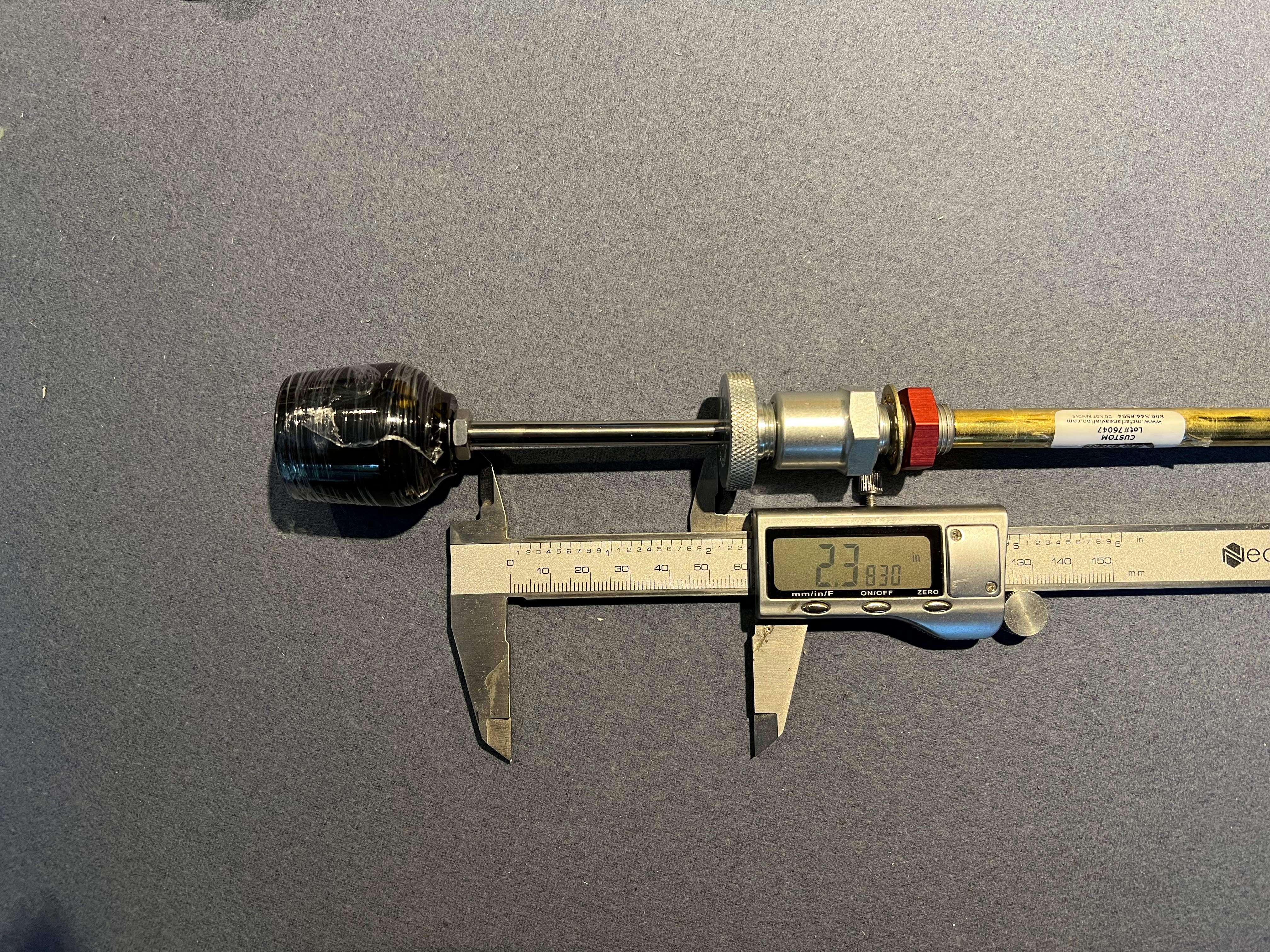
  • I get the throttle home, and start test fitting it.  The UL engine needs just shy of 2.5" of throttle travel.  My custom throttle has 2.38".

  • Well thats not going to work... I email pictures and call McFarlane.  According the the service rep I dealt with (who was super helpful), it was made this way on purpose to "maximize the overlap at the throttle end", based upon my drawing.  Well, the throttle calls out the minimum required travel / throw of 2.5".  Bottom line:  redesigned the throttle to get 2.5" of travel.

  • Above is old / new.
  • New throttle is ordered, and should have it within a couple weeks.
New throttle has arrived, and boy is she a beauty!  I messed up when I ordered originally and used the non vernier form.  McFarlane was very accommodating and built the new one as a vernier control.  Also, they sent the incorrect tool last time, and sent the new one at no charge.  The service was outstanding - zero complaints.

The vernier control version of the throttle is different.  The locking mechanism ships separately and needs to be installed.  There is a big note on the locking mechanism to NOT remove the temporary shipping shaft without the throttle shaft directly following it.  Of course I did, and all the roll pins came out.  Luckily they have a video on how to put it back together... disaster averted!

The nice part about the vernier control is you can mount it from the rear.  Doesnt matter now, but that may come in handy at some point in the future.

Nex challenge is the mounting bracket on the engine.  The stock UL bracket is for a bike style cable and sleeve.  Zenith has a bracket that mounts to the engine lift point location.  I am going to something similar.

First step is to make the plate that bolts on to the lift point.


I used a shape finder to get the curve around the starter.  The throttle mount point has to be about 3" back from the plate, and on a bit of and angle.  I made a template out of paper first, then aluminum to find the center of the holes, and then transferred that onto .063 4130 steel.  I want the plate as large as possible.

I am worried about the stresses on this bracket and vibration.  The location of the mounting holes is not ideal.  I put a bend in the left hand side of the bracket, and am going to add a small arm that goes over the top of the aluminum mount for some added rigidity.

The bracket is all tacked together.  Test fit.

Throttle fully closed.


Fully open.


Seems to do the job well.  Going to add a gusset to strengthen the arm.


Gusset added and everything tig welded.  Fits well and appears very strong.  No flex at all.

The bracket needs to filing and priming / painting - but will do that when I do the next batch of parts.


Friday, 26 May 2023

Intercooler


I ordered the intercooler from UL Power USA in the summer of 2022 when I ordered the prop.  Due to supply chain issues, price increases, change of vendors the brass tacks are finally hitting in late January / February of 2023.

The question was... orientation of the inlets and outlets.  The other Sportsman that is flying has his intercooler up high in the engine bay, aft of the engine, just under the engine mount.  He has air temp issues, and is trying to get more air to the plenum.

My tentative plan...

  • Enlarge the front openings in the cowl slightly
  • Use ~1/3rd of the opening to feed a 3" scat tube on each side.  Run that scat pipe in parallel with the cylinder heads and feed a plenum attached to the intercooler.
  • The big reason for doing this is it will all be fixed to the engine / baffles.  There will not be any hoses (well, other hoses) attached to the cowl, so the top will just come right off.  At least that is the theory / plan.
The plan has one potential flaw.  The plenum will be on the back side of the intercooler and push the air forward, and it will hit the ring gear.  The alternative is to push it back into the pumps, filters, and coils.  That is a bad idea...

Putting it on any angle just spreads the heat.  I think having it hit the ring gear (and mix with all the air coming down from the cylinder head baffles and go out the bottom) is the best compromise.

Below is the drawing I received from UL...


I mocked up the basic dimensions in cardboard so I could play with it.  So it was arts and crafts day... the dixie cups are the inlets / outlets.  I really wish the engine was on so I could play with it a bit more...

Note:  I had not planned on doing this, so I hurriedly clecoed in the firewall frame and engine mount.  This all has to come back off again... unfortunately.


The turbo that feeds the intercooler is on the starboard side of the plane, on the aft side of the engine.  The throttle body is on top of the engine, aft end.

Based upon what I know and what I can see, going straight up and down is the way to go.  1 90 degree bend from the turbo to the inlet, and then 2 90's from the intercooler to the throttle body.

Its always so much easier to say things like this... harder to achieve.

Intercooler has been ordered with 2 straight fittings going straight up.  I sure hope this is the right choice (I say that a lot...).

Now it's time to wait.  Lots can be done between now and then.

Intercooler finally received in April (3 months later...)


Mounting this beast is going to be a B$#&H.

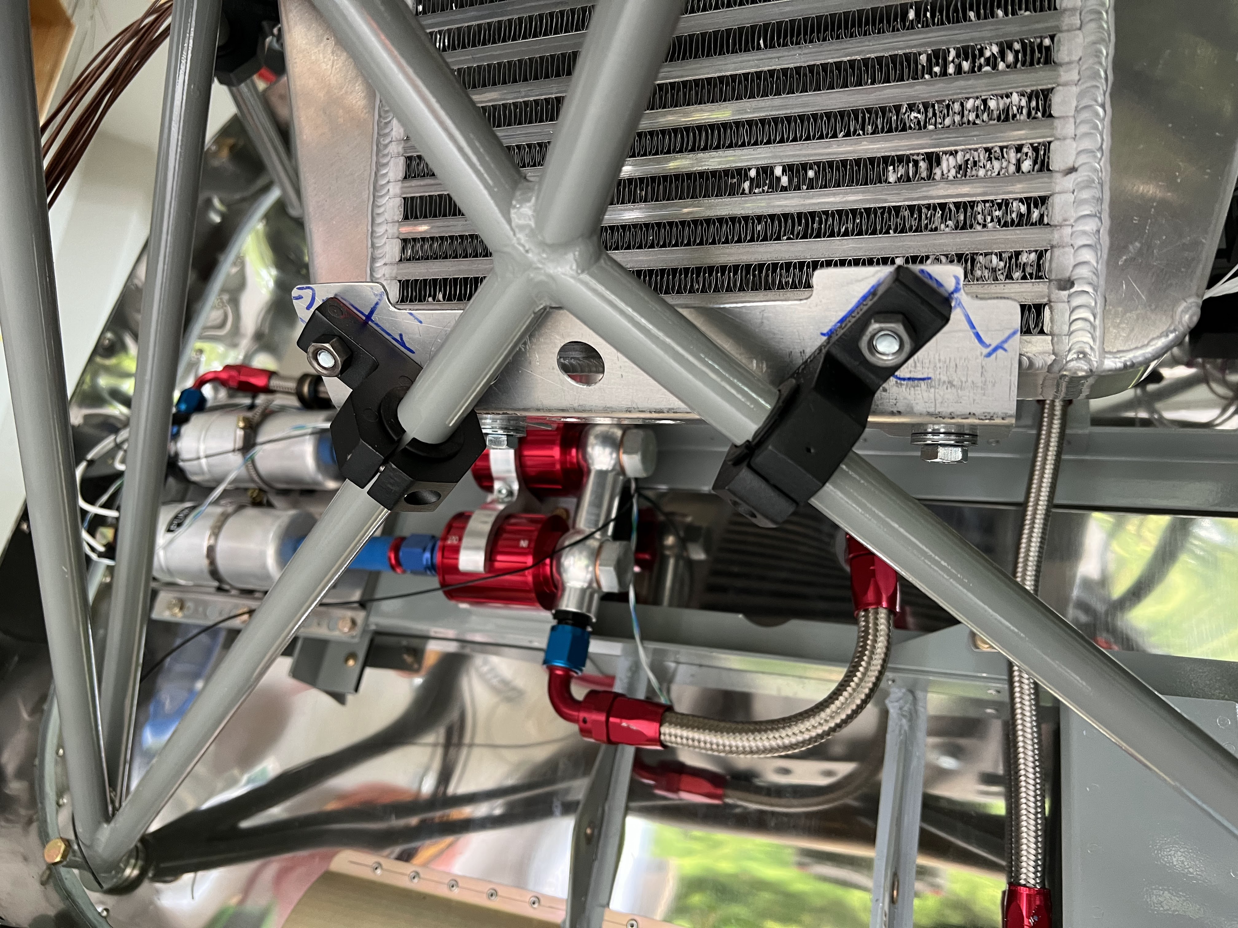
I bought some role cage mounts on amazon.  My tentative plan (until a better ones comes along) is to use 1" tubing, press the ends flat, and mount to the brackets clamped to the engine mount.  Like this.


Then weld brackets on to the tube at the correct angle for the intercooler.  I will probably have to tack them in place to get the angles right.

Fast forward a month or so... I have been working on the positioning of the intercooler.  Moving the bar back and forth to get the right angle to the turbo (so a 90 degree 2" hole will connect), positioning the intercooler left and right to not hit anything, etc.  The mount for the bar is now 11.25" along the engine mount from the firewall bolt head on both sides.  I moved it about an inch farther back.  The top cooler mount brackets are tie wrapped on so they can be moved.


I was a bit concerned with engine shake (on startup) after watching a 4 cylinder UL bounce around when the cowl was off.  Asked another Sportsman / UL builder how much room he has between the turbo outlet and the engine mount (I have 0.5").  He has less, and it has never hit and the engine does not shake.  Moving on.

So now its positioned fairly well, need to make the bottom bracket.

My original plan was to have a cross tube for both the top and bottom mounts.  However the top is so strong, having a 2nd one would be complete overkill.  So the bottom bracket will just be a bent piece of .063 aluminum to pick up the bottom brackets.


I will trim it down to reduce weight.  Just wanted to get it positioned and drilled.

Trimmed down with a few lightening holes.  May add a few more...


The mounting is nice and stiff.  It's not going anywhere, which is the point.

For the outlet of the cooler to the throttle body, I need 3 bends.  I also have to reroute the engine umbilical slightly. 

I bought 3 90 degree bends and cut them up appropriately, with a 2.5" piece of 2"OD aluminum as a coupler.


Next is the plenum.  Goals:
  • Light as possible
  • ability to remove when installed (I dont have enough room to get both the intercooler and plenum in together without taking off the engine - not enough room) on the cooler.
  • Leave room at the back to access the filters, etc
  • Flat side pieces for the scat tube inlet.  I want the tubing as big as possible - ideally 3"
I know there are so many ways to build a mold.  I used MDF (aka particle board).  Its strong, straight, easy to work.  I'm calling my mold the dog house (for obvious reasons).


My original plan was just to wrap it in packing tape and lay it up.  But, I know it will come out better if I properly finish the mold, fill the gaps, paint it, etc.  So I am.  All filled and ready for sanding.


Using a paint and primer in one... will need a couple coats and sanding.


Next it to build the bracket that will capture the plenum on the intercooler.  The one data point I have simply RTV'ed the plenum to the intercooler.  That is not my plan.  

My plan (hopefully) is to build a bracket that wraps around the intercooler with flanges that captures the plenum.  That way its removable.

The starting point for the bracket is to simple mimic the shape of the intercooler.  Again, I built the mold out of MDF, cut the fiberglass, coated it with resin and waited... and waited.  It never hardened.  I took it from a brand new can that I thought was promoted - it was not.  So mixed a test batch of 100g and promoted it and activated it, worked fine.  So cleaned everything off and tried again.


This is too large and will be cut down to fit, and will have a big hole cut in the middle.  Bottom line, this will wrap around and seize the intercooler and have flanges to capture the plenum.  Add a dozen or so nutplates and the plenum will be removable.  2 layers of bidirectional glass, with some peel ply on top.


Well, failure.  The part wont come off the mold.  I tried everything I could think of, and the part and mold are damaged beyond repair.  Time for plan B - aluminum.  Going to go with the same basic design.

What I did wrong:
  • The mold was too strong.  There was no way to get the part off.  No way to wiggle it out.
  • I used wax, and probably should have used mold release.
  • Should have made the mold out of foam so I could chip it out.
The big issue seems to be the corners, which are rounded with a 1/2" radius.  There is 4 layers of glass on all the corners.  Its super strong.

I have wasted about 3 half days on this.  Very frustrating.


The layout for the end caps will be the most challenging.


Looks about right.  Now just need to drill it.


So it fits in the spot intended and there is enough room to get stuff in and out.  The intercooler goes in first and the hoses attached, then the plenum will fit up through the bottom.  Attaching it will be a bit of a challenge.

New mount received that is made from 4130.  New holes drilled, and mounts tacked in place (forgot to take picture).  Now its onto finish welding.

Progress made on the plenum mount for the intercooler.


The plan is a C shaped bracket tha wraps around the intercooler.  The holes above are for the intercooler mounts.

After bending.  Note:  I have to cut a window in the mount for the cooler.  Have not gotten to that part yet, but will.


Fit to the intercooler.


Now its onto how to mount the plenum to the bracket (that wraps around the intercooler.

Because of restricted access, I am going to try and make a slot at the bottom that the plenum slots into.  The top will just be a flange with nutplates.


All of the bracketry is going to be flush riveted on the bottom, as it has to sit against the cooler.  I cant assemble the whole thing together now until its riveted.

After staring at the intercooler bracket and looking at the best way to attach it to the plenum, I decided to make a new one that is slightly larger on the face of the cooler.  It just wasnt wide enough to get some flanges installed and have everything tight, so I made a new one that is about an inch wider.  To do so, I have to go around the inlet and outlets on the top.


This time I precut the window for the cooler element.  I could have cut it after, but much easier to do before its bent.


Fits well.  Needs a bit of trimming here and there, but I have enough meat on the sides now to attach some angle brackets / flanges to grab the sides with nutplates.

As a side issue, noticed that the Advanced Flight Systems implementation of the UL CANBUS stack is missing the manifold air temperature.  This will be key in assessing the efficiency of the cooler.  Feature request submitted to AFS to add this data point.  Advanced says 2 to 3 weeks until beta software that includes the feature!

Flanges installed on the new plenum mount.


Upside down view.


The next step will be the intakes for the plenum, and I'm not sure what size yet.  This is going to sit now until I get the baffles on, and cowling fitted.