Search This Blog

Wednesday, 28 December 2022

Advanced Deck, Foreflight and Wifi

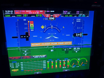
I purchased the Dynon wifi adapter as part of my avionics package, but had not getting around to plugging it in (that is pretty much all that is required from a physical standpoint).  So needing a motivation, I plugged it in.  The setup is easy... give it an SSID and password, and thats it.

I joined the network from my phone and opened Foreflight.


Well thats cool.

So I did up a basic flightplan on my ipad, connected it to the aircraft wifi, and the option shows up under 'Send to', 'Panel'.


The panel then wants you to confirm that you actually want to load it.


Piece of cake.

When airliners fly over, I get their ADSB feed in the shop.  Now I get it on both my ipad, and Advanced displays.


The only thing that is not working is my aircraft GPS.  There is a foil lining under our tile roof, so there is no GPS connectivity in the shop, so the altitude on foreflight is showing -32000 ft.

Monday, 26 December 2022

UL Power - Turbo Pressure and Wastegate Pressure Ports

The UL Power Installation needs a couple pressure ports for sensing.

  • 1 is plumbed from the throttle body to the ECU (aka turbo pressure)
  • 1 is plumbed from the throttle body (which appears to be at the same point as the above point) to the boost controller (aka turbo pressure)
  • 1 is plumbed from the waste gate to the boost controller, but it is T'ed in with the above line coming from the throttle body (I believe this is turbo pressure, mixed with waste gate pressure)
  • The Aux box has a port that needs to be plumbed to a static source.  I am NOT plumbing this to the main static system, due to the Canadian regs requiring a 2 year pitot static test.  I will probably end up plumbing in a 2nd static system just for this line, but that is TDB currently (this one is just ambient pressure)
The bizarre part of this... the lines for the ECU and boost controller are different types.
  • ECU:  Appears to be a standard AN3 fitting with stainless steel braided line.  
  • Boost controller:  Silicon hose.  2 ports on the boost controller, 1 to the throttle body and the other to the waste gate.
This is the UL documentation (just one page that attempts to show it all):


The engine comes with the hose and ends, but nothing to bridge the firewall.  I used an AN-3 bulkhead fitting.  Before anyone gets all judgementy on me, my plexiglass firewall is still in place so all of this is considered mock up.


Connection to the ECU (looking down from where the forward windscreen would be).


Engine connection


For the two lines coming from the boost controller (one to the wastegate, and the other to the throttle body), since they are just 1/4" hose I use qty 2 AN-4 bulkhead fittings, with qty 4 Phenix push on fittings.  I used these on my header tank, and they are impossible to get off.  And I mean impossible.


These two fittings are outboard of the firewall accessory frame (which lines up with the cage tab mounting inboard of the engine mount.  Almost a straight shot from the boost controller sitting on the shelf, just aft of the ECU)/

All of this is just temporarily attached for overall fitment.

One more day until the engine comes off (fingers crossed, weather dependant).

What's left to do tomorrow:
  1. Throttle firewall penetration
  2. Cabin heat cable firewall penetration
  3. Alternate air cable firewall penetration
Then I should be good to go... fingers crossed.  Then it all comes apart...


6 years: Dec 26, 2016 to Dec 26, 2022

6 year anniversary of my Sportsman project.  It all started 6 years ago today with the rudder.

What has been accomplished in 6 years...???

  1. Slow build tail (rudder, horizontal stab, elevator).  Purchased used (unopened) in Canada, saved a bunch of money.
    1. Tail complete except for tips and paint
  2. Slow build wings.  Purchased new from the factory.  At the time, this kit was $17.5K USD, now its 25K USD (43% increase).  Quickbuild wings are now 47.5K USD.  OUCH.
    1. Wings complete, except for wing tips, paint and fuselage wiring integration.  Wings closed, struts cut, etc.
  3. 'Ultra quick build fuselage'.  Quick build fuselage, that had a bunch of work already done (doors, firewall blank, control cables, bulkhead A, horizontal stab mounts and closeouts, etc.  Got a really good deal.  Purchased in 2019, but the real work started in early 2021.
    1. Tail dragger conversion complete (T3, Pekola Tundra Light Tailwheel, tailwheel service bulletin)
    2. Interior completely repainted.  This took 2 weeks of disassembly, prep, masking, paint, cleanup and reassembly.
    3. Tail pull handle.  Such a cool feature... but I dont want to do this again.
    4. Vertical fin spar service bulletin
    5. Brake master cylinders, park brake valve.  Still need to run the lines from the valve to the callipers.
    6. Seat tubs cut and fit (plus Zach's seat pan inserts)
    7. Overhead console / light / tailwheel lock.
    8. Rear seat assembly and tunnel covers (100% made from scratch)
    9. Rear baggage floor.  Zach special... but needed a lot of fitting and other touches to complete.  2 weeks last Xmas.
    10. Forward tunnel covers
    11. Header tanks and fuel line plumbing
    12. Overhead cable cover
    13. Instrument panel design, fitting, cutting and wiring (90% complete).
    14. Control sticks, grips and wiring
    15. Autopilot servo tray, mounting and wiring.  Control cables not complete.
    16. Glareshield fitting complete, holes cut for fans, fan wiring complete.  Needs upholstery and to mount compass.
    17. Temp engine fitting
    18. Firewall frame - custom frame for batteries, coils, fuel pumps, filters, gascolator, etc.
    19. Cowl extension (still lots of work to do, but the cowl is extended)
    20. Front / rear seat fitting (front done, rear not fully complete)
    21. Static ports installed, and static line run - still need to finish pitot and AOA
    22. Wiring schematics - 80% complete.
There is probably more, but those are the big items.

Other non-aviation projects completed during the same timeframe:
  1. Full bedroom set (bed, headboard, side tables, dresser)
  2. Kitchen nook
  3. 3 years of quarter midget racing with my son
  4. 2 year build of a street stock, and 1 season of racing
  5. Small amounts of flying... like 15 to 20 hours a year small.
  6. Hanger purchase and remodelling (floor paint, mezzanine completion (new stairs, new railings, flooring, drywall, wiring, solar power)
  7. Full time job plus business travel (travel non existant during COVID...)
OK - thats enough.  No wonder I am always tired LOL.

Reflecting on the decisions I made.  What would I do differently...
  • Tail:  I wouldn't change anything.  Saved money, and learned a lot.
  • Wings:  Same as the tail.  The slow build kit is half the price of quick build.  Building both wings at once was the right move - but takes more room.
  • Fuselage:
    • I am questioning my decision to go UL power (not backing out now... but...).  I had to design everything, and countless modifications are required.  This added 6+ months to the build minimum.
    • Panel:  I thought going advanced would save me time, and if I had done a standard install that would probably be the case - but everything I did was custom.  The wiring between the avionics and UL ECU is 10 lbs of poop in a 2 lb bag.  Took a long time to figure it out.  If I had to do it again, I would have gone Garmin.  Canbus is soooo slick.
    • Buying a 3rd hand fuselage saved me money (like about 40%), but I ended up redoing a lot of things already done - or at least taking apart and checking everything.
Keys to success:
  • Tools:  
    • Bandsaw is huge.  I use it a lot.
    • Tablesaw is super handy for building jigs.  Takes up a lot of room in the shop, but I used it a fair bit especially during the wings.
    • Rivet squeezers.  Having multiple is awesome and saves changing bits all the time.
    • Pneumatic rivet squeezer:  Super awesome.  Dont use it much, but when I do it saves lots of time.
    • Right angle drill adapter.  I'm on my third.  They are cheap with plastic gears.
    • Belt sander.  I do not know where I would be without this.  Use it all the time.
    • Break and sheer.  I have access to one, and would not have done as many parts myself without it.  Its a 20 min drive each way for me.  If I didnt have that, I would have bought a small bench-top version.
  • Work Space and Storage
    • Having the project at home has been great.  
    • The mezzanine in the hanger is Sportsman parts storage for big stuff.  So helpful.
    • I took over a room in the basement for part storage.  Nice to be able to store finished parts and just parts close at hand.  I need to get better at organizing.
  • Amazon!
    • I cannot understate how awesome Amazon has been.  If I need something that just broke, a tool, drill bits, etc being able to find it and order while you are in the shop and go right back to work on something else is just massive.  I have saved so much time not having to drive around and find stuff.  They dont have everything needed, but for common stuff its just awesome.
  • Supportive family
    • This is huge.  If the family is not on board, building will be slow and progress difficult.
  • Local knowledge
    • I am very lucky that I am surrounded by other builders.  Having access to knowledge, sharing tools (works both ways), and getting help when needed is massive and cannot be understated
  • Specific knowledge
    • I did not want to pick an orphaned kit (where the manufacturer is out of business).  Having access to parts and support is key.
    • Having an active forum comprised of other builders is key.  Both being able to search for solutions, or ask specific questions when you get stuck.
    • Local EAA chapter or the like.  Huge resource that can help with knowledge, tools, experience, etc
  • Plan the work, work the plan
    • When you start a project (you need to consider building an airplane 1000 small projects, and not a single large one), do as much research as possible in advance.  Order parts, ask questions, get advice.  Doesnt always work, but works more than it doesnt.
  • Document, Document, Document
    • Have a build log, and keep it up to date.  It's useful for some many reasons:
      • Helping others
      • Keeping motivated
      • Remembering what you did
    • Lots and lots of pictures.  Being able to look back and see where you were 3, 6 or 12 months ago is huge for me to keep motivated.  When I get stuck on something, knowing that I have solved problems in the past and gotten through it is key.
The big question I keep asking myself:  Would I do all this again?  Maybe.  While I have never bought an airplane, when i see other people that have purchased a used airplane there is always a list of things they want to change, dont like, upgrade, etc.  Hopefully i am getting what I want and the compromises will be minimal.  What I regret the most is the time spent not flying.  I like working on projects, but this is by far larger than anything I have ever done.  I am convinced I will not build another airplane (famous last words).

OK - I have blathered on a lot.  I wrote this more for me than anyone else as I need some motivation.  6 years is a LONG time (almost 12% of my life), but the end is near and I need to keep pushing through.

Happy holidays.  Going back to the shop...

Friday, 23 December 2022

Wiring / Cleanup

I have been working on cleaning up the wiring mess I created for myself.  I call it 10 lbs of poop in a 2 lb bag.  But realistically, if you add up the weight of all the avionics and wiring its probably closer to 30 lbs all in.  Not that I have weighed it.

Having a super light engine, my plan was to move as much forward as possible to help offset the weight.  Between the panel and the firewall are the following components:

  • 2X 10.3" displays
  • Backup EFIS
  • Prop controller
  • Advanced ACM
  • UL ECU, boost controller and aux box
  • COM radio
  • Room for IFR GPS and NAV/COM
  • Avionics backup battery
  • Header tank
  • Audio panel
  • EMS
  • ADSB receiver
  • Hall effect sensor
  • GPS 2020 receiver
  • Skyview expansion bus
  • And all the normal 'stuff'.
Add all that together, and its 10 lbs of poop in a 2 lb bag.

Top down view of the mayhem...


The relatively clean panel hides the mayhem that hides behind it.

The GOOD news is everything works.  All the avionics are connected, the ECU is talking to the EMS, all the controls on the sticks do what they are supposed to.  Radio / audio panel / audio all works.  Servos are talking to the system.  Prop controller has power and just needs connection to the hub.  All of the lights (nav, strobes, taxi, landing, panel, overhead) all work.  Pitot heat is ready to go once the wings are attached and wiring finished.  ECU indicator lights.  Circuits for the engine and transfer pumps.  It all works.  Yay me.

It's not 'pretty' like I hoped it would be.  But to move the weight forward and contain it all between the panel and firewall is an extreme challenge.  If I could get rid of the ACM and use CANbus only, it would be way neater - but that is not the path I chose.

Once the weather dries out a bit, the engine will come off and the real firewall will go in, and then I can finish up the firewall forward wiring (fuel pumps, batteries, relays, shunt sense wires, prop controller, etc)

I am tired of wiring, and look forward to building parts again (which is totally ironic).

Merry Christmas.

Thursday, 22 December 2022

Update...

Progress is being made... albeit slowly.

The wiring on the 'Longnose' Sportsman is pretty much done.  The last bits remaining:

  1. Wire fuel pumps from the switch to the pumps.
  2. Alternate air switch / panel indicator
  3. EarthX battery fault wires
  4. UL regulator to main bus
And thats pretty much it.  Everything else is installed, wired an functions as expected.

I have the next 1.5 weeks on vacation, and have a few goals to accomplish:

  1. Clean up the rats nest of wiring.  OK, its not THAT bad, but needs some TLC
  2. Finish the last of the firewall penetrations and determine routing for the prop controller to prop cable, EGT's/CHT's, cabin heat cable, fuel injection return, boost controller lines, and thats about it (as if that's not enough LOL).
  3. Pull the engine and put it back in the crate
  4. Drill the 'real' firewall
  5. Rivet the flanges on the real firewall
  6. Adhere the firewall blanket
  7. Install the firewall and rivet it in place.
  8. Rehang all the firewall components (regulator, coils, fuel pumps, relays, batteries, etc)
  9. Reinstall the engine
Is all that doable?  Maybe - we will see.  I think I can get 1 through 7 done before January 2nd, maybe more.  But you have to have goals, right?

IF I can get all of the above done, then its onto engine / firewall forward 'stuff':
  1. Oil cooler mount and lines
  2. Oil cooler opening in the front of the cowl
  3. Intercooler mounting
  4. Ducting for the intercooler
  5. Air intake and filter mounting / plumbing
  6. Alternate air inlet
  7. Finish the exit air ramp on bottom of cowl
  8. Cowl 'finishing'
  9. Cowl fasteners
  10. Windows (front, top deck, doors (x3), fuselage) - the front window will be last (and probably just temp bonded until after first engine run)
  11. Brake lines from park brake valve to calipers
  12. Throttle and engine throttle (capture) bracket
Once all that is done, its off to the airport.  Hoping for mid 2023, then its onto final wing integration (wiring, fuel lines, hatch covers, wing tips, lights) and final wiring, etc for the tail.

80% done, 80% to go.  Will be finished on Tuesday.  Just not saying which Tuesday... 

Saturday, 17 December 2022

Control Sticks

I am at that point in the build where progress is frustrating because I have overcomplicated a lot of things.  I decided to go with the Infinity Stick grips, and load up on functions on the grip itself.  They are a really good grip it a lot of ways.  Easy of installation and wiring is not one of them.

Well, thats not fair I guess.  The installation is fairly straight forward... but you have to trim 1" off the stick to get it to fit under the panel, drill a big hole for a plastic bushing, and a slot for the wiring to pass through.  But it nicely clamps onto the stick...

First things first... you need to set the fore / aft position of the stick.  That means you need uphostery (which I ordered) first, then the sticks have to be drilled to the yoke.  This is the part I have been avoiding because I was unsure how to tackle the issue.  Since I have the fuel lines installed, you have to work around them.

So today after (what seems like months) of indecision (and talking to other builders), I tore into it.  The holes have to be drilled through the yoke and stick, but I couldnt get my alignement jig on the yoke, so that means freehand drilling, which is prone to errors, plus you have to line up the sticks and I dont have the wings attached to center the ailerons.  But, there is some adustment on the yoke, and turnbuckles.  So I decided to just center the yoke with some wood blocks, center the sticks with a board (per the manual), and carry on bravely.


After marking 3/8" in from the yoke weldments, I drilled 3/32" pilot holes through the top only (yoke and stick) and clecoed them in.  That should hold everything in place.


I dont have the right length drill bit for the forward hole, but did for the aft (again, working around the fuel lines).  So both aft holes were drilled and a AN3-14 bolt dropped in replacing the cleco.


With the right length bolts I can proceed.


To the wiring.  UGH.

The infinity grip the following options:
  • 4 way hat switch
  • Trigger switch
  • Left and right thumb switches
  • Middle thumb switch
  • Pinky switch

After thinking a lot, and consulting the forum I decided on the following:
  1. 4 way hat switch:  Pitch and roll trim
  2. Trigger switch - Push to talk
  3. Left and right thumb switches - Left(a):  Autopilot disconnect / CWS.  Right(b):  Momentary toggle - forward, COM1 flip flop.  Aft - COM2 flip flop.
  4. Middle thumb switch - Audio panel swap from COM1 to COM2 and vice verse.
  5. Pinky switch - Transponder IDENT
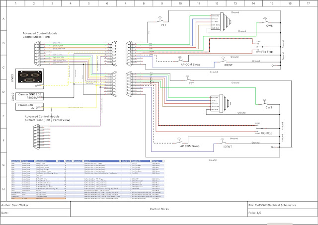
That equates to a whole bunch of wires.  Items 1, 2, 3a are handled by the ACM wiring to the 'control stick' port.  Items 3b, 4, and 5 need to be wired directly.  The transponder IDENT will be handled through the ACM using a general purpose input.

Here is the wiring diagram for just the sticks.


This is not going to be fun.  10 lbs of poop in a 2 oz bag.

Grips mounted to the sticks after drilling.


Sticks fully drilled, ends cut and filed, grips mounted and wires fed through.


The Infinity Stick Grips are very nicely made, as assembled really well on top of the stick.  After about 15 disassembles / reassemblies I am reasonable good at it.  The issue is the wires... there are so many wires, and if they get caught in the channel for the stick, or against one of the bosses that the screws go through it wont go together.  If any little thing is wrong, you are taking it all apart again. If you want a grip that you just mount on the top of a stick, this is not the one for you.

Next is to connectorize the cables from the sticks and integrate in the ACM, Dynon Radio, Audio Panel, etc.  I thought I had enough connectors, pins and housings, but apparently not.  Ordered from Digikey today.

Connectorizing was not fun (I have an aversion to connectors anyway, specifically getting pins out of shells - never goes well).  There is a colour code for the wires, but there are duplicates.  For the most part, black is ground (but not always), and there are multiple red and blue wires.

  1. Sorted through all the wires and found the ground (using an ohm meter), and separated them from the pack
  2. Tied all the ground together on the stick side using solder sleeves.  There are 6 ground - so 3 into 1, then 2 into 1, then that wire went to the connector.  Sleeves are hidden under head shrink.
  3. Checked functionality of every switch at all points in the process.  Would really suck to get everything done and have a busted wire or bad ground.
  4. Connectorized the end using a d-sub 15.
  5. The connector will fit through, but without the shell, and it has to go through sideways.  I left enough bare wire to get it through.

Onto final wiring.  I have the ACM harness for each stick, but it doesnt come with IDENT, COM flip flops (x2) and Audio Panel swap.  These all have to be added to the harness.


So I cut open the pilot side harness, and added the 3 wires.  Oh what fun...

These 4 wires need to go to various places:
  • IDENT:  Goes to a PFD input on the AC Rear Connector
  • COM 1 SWAP:  Goes to the Dynon radio
  • COM 2 SWAP:  Will go to the yet to be purchased GARMIN NAV/COM
  • Audio Panel SWAP:  Goes directly to the Audio Panel.
I put everything together to test, and it all worked - except the Audio Panel COM SWAP.  It seemed like it would work every once in a while, but not like I expected.  I checked with both PS Engineering, and Advanced - but at the end of the day I just miswired it.  I had it connected to pin 21 on J2, when it should have been pin 20.  The issue was getting the connector apart on the audio panel without losing any hardware in the fuselage or panel.

To finally everything is done.  Sticks are wired, connectors attached, everything tested good.  Sticks are bolted in place.


Starting on the cleanup now.  It sure needs it.


Wednesday, 14 December 2022

BNC Connectors

I have an aversion to all connectors.  They always seem to make my life hard, and I mess things up and cannot get them apart.  The top of the list has been BNC connectors, because I didnt understand them.

A buddy of mine showed me how to put on a BNC, and still I messed them up.  You have to strip 3 times - center conductor, inner jacket, outer jacket - I get that - but how long does each of them need to be?

I have 3 types of connectors for the Sportsman

  • BNC Male
  • BNC Female Bulkhead
  • TNC Male

I found it extremely hard to find the correct assembly instructions for each type of cable.  After searching, I found it for the Amphenol BNC male and TNC Male, but not the BNC Female Bulkhead.

So I measured everything and mapped it out (BNC Female Bulkhead).


Dimensions are available if you have the part number.  Below is the Amphenol TNC male.


This may be 'old hat' to some, but i was just inexperienced - and after wrecking some pins I thought there has to be a better way.  Now I can do a BNC and not waste any parts.

Happy days.


Tuesday, 6 December 2022

CANbus / UL Power Integration

Finally got around to wiring the Dynon EMS-221 to the UL ECU.

The Dynon manual does not give a lot of detail, except the pinouts - and there are omissions.

Here is what came with the engine and harness:


On the EMS side, the manual gives some info on UL Power installations, but it is not overly helpful.  However, I asked Advanced specific questions about the ground wire, 120 ohm resistor, and shield from the UL side.  Below is what I got back.


This is what I followed.  I added the termination resistor (however, Advanced noted that they probably have many Rotax installs in the field with no resistor, and no issues), ground, and tied the shield to the EMS ground.

When I fired everything up, there was no obvious was to see the CAN bus status.  I poked around forever and nothing was obvious.  I had a 2AM brainwave that I needed to change the engine selection.  My PFD was set to '6 cylinder turbo', when it should have been 'UL 6 cylinder turbo'.  As soon as I changed that, I now had the option to select CANbus inputs for the different gauges and I could see that CANbus was connected and working.


As you can see, there is an OIL PRESSURE A and OIL PRESSURE B - where A is valid, and B is not.  I assume B is for if you have a 2nd ECU.  Confirmed on 12/6/2022 that the 'B' lane is for a 2nd ECU..

Everything appears to be working.  I have to set the limits on everything still, but that can wait until closer to first engine start.


Wednesday, 30 November 2022

UL Power - ECU Wiring

I thought the UL ECU wiring would be simple, and in some ways it is simple.  But as always, the devil is in the details.

Power:  The ECU has 6 wires that all need to be attached to an ECU switch.

Ground:  The ECU has 5 wires that go to ground.

FPCR (Fuel Pump Control Relay(s)):  The ECU can control the pump(s).  I opted to do so, but there is a 2nd bypass circuit around the relays just in case.

Ignition:  Circuits for left / right or 1/2 coils to switches (or a standard key switch).  Grounded they are OFF, open they are ON - just like a mag.

Aux box:  Provides ambient pressure.  Plus other things, but this is all I am using it for.

Boost controller:  Control line from the ECU to the Boost Controller, plus power and ground.

CAN-bus:  Data lines to grab engine data via CAN.

RS-232:  Separate RS-232 connection for an EFIS feed, or to use the UL-READ software.  I need to order this cable.

Discrete engine inputs:  Separate inputs for Engine RPM and fuel consumption.  I am not using these, as they are provided over the CAN-bus.

Dummy lights:  2 LED's.  1 for 'check engine' (which indicates a sensor fault), and 1 for 'low battery'.  I planned for both of these in the panel.  The ECU only provides a ground to activate these LED's, power is separate.

The above is the basic lay of the land.

Current schematic below.


At present, everything is wired except the key switch.

The challenges:

  • The ECU is mounted on a tray forward of the instrument panel.  If it needs to be removed, take out the MFD, remove the two harnesses, loosen the bolts and its free.  You should be able to do all this sitting upright in the seat.
  • Making the above happen is a challenge.  I had to route all the wires in two consistent bundles (one firewall forward, and one for the cockpit interconnects) and not running in 4 different directions.
  • To do so, I fabricated some wiring 'braces' that everything is tie wrapped to.  But its all very condensed. Hopefully this works out.
Progress:
  • Everything is wired for the ECU, and it powers up (the LED's flash upon startup).
  • The next big step is to see if the ECU connects to the CANBUS on the EMS221.
  • The wires are not in their final position.  I want to make sure everything works before doing the final tie wraps (hence no pictures, it looks pretty ugly right now)
What's left to wire:
  • Magnetometer:  Cable is run, but needs to be shortened (ordered it too long)
  • Fuel tank probes.  Wires to the EMS, needs to head out to the wings.
  • Sticks:  Sticks themselves are wired, just need to route them and connectorize from the ACM (plus the pull downs from the audio panel, com, and ACM aircraft rear connector
  • RF / antennas:  VOR, 2xCOM antennas.

Probably forgetting something, but its almost there.


TO/GA Button

I had figured I would eventually figure out where to wire the TO/GA button (Take Off / Go Around).  That never happened, so I needed to ask Advanced.  Well, that feature is not available yet - coming in release 17 (current release is 16), with no planned delivery date that they would commit to.  Well I am not ready to fly yet, so no big deal.

The button needs to be wired to one of the PFD inputs on the Aircraft Rear connector:

From the Advanced Manual:

Will use PFD2, pin 14.

I was really nervous about opening up my AC Rear harness, but of course it was a non issue and took 2 minutes.


Last step is testing it, but that will have to wait until the displays are back in.


Dynon EMS-221 Wiring

As Advanced Flight Systems is part of Dynon, it stands to reason that Advanced would use the Dynon EMS (Engine Monitoring System) unit.  Dynon has 2 flavors - the EMS 220, which is the standard unit - and the EMS 221, which has CAN-bus connectivity.  I need the 221.

The EMS-221 has 3 connectors:

  1. DB9 for the Skyview Network connection
  2. DB37 for all of the engine wiring (except CHT and EGT)
  3. DB25 for CHT and EGT probes
1 and 3 are straightforward.  2 is interesting.

The UL ECU passes most of the engine data over the CAN-bus connection.  From the UL manual...


Bottom line:  There is very little for the EMS-221 to do, other than getting the CAN-bus data from the ECU.  Here is the pinout (only yellow items are planned to be used)


Basically current, voltage, fuel tanks, and CAN-bus.  I have a question into Advanced on whether or not I can use the 2 voltage pins, as these are on the ACM as well - so these might not be needed).


Everything is wired, except for the tank sensors.  Kinda need the wings for those...

I put the EMS on the bottom of the right hand avionics tray, thinking this would be easy to get to. Yeah, right.  Its not impossible, but definitely not easy.  Removing the ECU makes it easier.

Fuse Panel

I have a couple circuits that I dont want to run through the ACM.  Why you ask?  Well, what if it fails.  Or, what if the current draw is high and the function is not essential?  

Things that are going to be fused and not through the breaker panel or ACM:

  1. LED indicators.  2 for the UL ECU (Check Engine and Low Battery - the ECU does not provide power for these, only a ground to activate them).  Plus another for the Alternate Air Inlet on the airbox.  Dont need carb heat as the engine is injected, but need an 'emergency' air source if the filter gets iced up.  1A circuit
  2. Header tank warning lights.  If the ECU dies, I want these alive and functional.  Another 1A circuit
  3. Seat lumbar support.  It has a small pump and inflates/deflates the bags in the seat.
  4. Seat heaters.  I am a wus.  I like seat heaters.  These draw more than the ACM has capacity for.
  5. Other stuff down the road.  Will be nice to have a place to get power that is somewhat readily accessible.  2 spare circuits.
I found a really nice automotive style 6 fuse panel that is small and light, and has indicator lights as to their health.


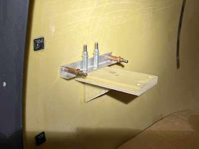
The plan is to mount it on the starboard side of the fuselage, just above the rudder pedals on the side of the fuselage.  The original plan was to make a plate and attach it to the cage tubes with adel clamps.  Well, I hate adel clamps, and mounting it up there with the bulk of the avionics installed would be a nightmare - so I decided to bond the bracket to the fuselage.

The bracket is a simple hat shape.  The tabs pick up the holes in the fuse panel, and the bulk of the bracket will be epoxied on.  The below pic is the bracket clecoed in place, ready for bonding.


Because its winter here, I need enough heat to get the resin to cure.  Luckily I have a big heater in the garage, but it will cost me.  The bracket has already been fit to the fuse panel so it should just screw in once cured.  I waited until a relatively warm day (aka 10 degrees C) to do this.

Done and first circuit wired (power for LED indicator lights and header warning lights).


Wednesday, 23 November 2022

Instrument Panel Redo (Carbon Shroud Only)

 It's a long and sad tale, but I had to replace my carbon panel with a new one.  Which meant cutting and fasteners all over again.  Carbon fiber is itchy... do not recommend cutting it and then going to bed.

The good news is everything is faster 2nd time around.  In 2 evenings I had everything cut and most of the fasteners installed.  I have to make new brackets for the nutplates on the switch plates, because of the switch plate dimensions, standard nutplates will show the rivets in the carbon.  Hopefully this too goes faster 2nd time around.


I am finally (almost) back to where I was in April (its now August).  Still missing a few fasteners that will need to be riveted in later.


I have been wiring like a madman for the past 2 days.  The aircraft front and aircraft rear ACM connectors are done.  The trim and flap connector is done on the ACM end, plus the aileron trim wing bulkhead connector.  There is still a ton of wiring to do.  Like days and days more.  Plus the engine wiring integration (which should be relatively easy... famous last words).

Everything is working as before, except I have added some wiring.

  • Autopilot servos:  Not working.  The ACM says they are drawing power, but the Skyview network cant see them.  Troubleshooting with Advanced. Fixed and working.  Factory harness was wired incorrectly, and I missed it.
  • Recognition light.  Working.
  • Wing wiring to bulkhead connectors.  Working
  • Glareshield fans.  
  • Overhead cabin light
  • Compass light
  • Aileron trim.  Not tested
  • Elevator trim.  Not tested
  • Flap position sensor.  Not tested (potentiometer not yet installed)

The last piece to mount is the magnetometer.  I dont know why, but I have been dreading this.  Used some foam / glass test pieces I had and just chopped them up.  Simple and light.  The below picture is bonded to the fuselage.  The aluminum bracket is just for placement and will be removed.


Rudder Stop Plate

 The rudder was finished very early in the build - well, it was actually the first thing I build in 2016 (now 2022).  Need to fabricate the rudder stop plate, and check the travel / deflection.

Fabricating the plate was easy enough, following the manual.  Fitting it to the rudder was pretty easy as well.


I was worried about bending the ends, but that turned out pretty easy as well.  I took a piece of 1/8th flat stock and rounded the corner, then clamped that along with the plate to the bench and then just bent it with my hands.  Turnout out perfect.  The manual calls for a 15 to 20 degree bend.  The first one took 3 attempts to get it there.  The 2nd was a one shot deal.

I drilled the aft holes to 3/32 and put 3 clecos in, then mounted the rudder.  The target is 25 degrees of travel, +/- 1 degree.  However the manual calls for initial fitment without the stop pad.  My fuselage already had the pads in place, but I then did the SB to add the stiffener which required drilling out the pads and remounting on top of the stiffener.  So my initial reading was 20 degrees.

Again, the manual calls for taking 1/8" off the stop plate to account for the pad, which I did.  That got me to 23 degrees.  A bit more filing and I got to 25.


Both the elevator and rudder stop plates need to be cleaned, alodyned and painted.  I have NOT checked the elevator travel yet, as the horizontal stab and elevator are at the hanger.  That is a job for another day.

But the rudder stop plate needs to be drilled up to 1/8" holes, finished, and riveted.

Glareshield

 I keep waiting to simply 'install' something, that doesn't require cutting, drilling, grinding, etc.  After 5 years of cutting, drilling and grinding I think I'm due.  Well, today is not that day.

I bought my fiberglass glare shield from Glasair in January 2021, along with the panel blank.  I kind of assembled everything when I got it in March, and it didn't fit.  Well, that was just to make me feel good and I had lots of work to go until I needed to put it in.  That time is now.

After the issue with the panel misalignment were corrected, I HOPED it would just slip in.  NOT.  It does not fit at all.  Further, the instructions (which did not come with it either, but I found on the forum doc library) don't say anything about cutting.  After checking with a few builders, yes it needs to be cut.

Here is the starting point.

I made a paper template that is the same size (and non symmetrical shape) as the blank.


Next the template goes into the glare shield location.  I marked with a pen below the window opening, and then added ~1" after the fact, cut to the +1" line.  


In some areas I took off a couple inches, in others nothing.

The trick seems to be getting the depth of the glare shield right first, because that changes everything else. I worked on this in bits and pieces, where in hindsight should have focused on this first.

The big trick is getting around the cage tubes on either end of the panel.  That took the most time.

A fellow builder told me its like doing the windows... fit, mark, trim, fit, mark, trim, etc, etc.  I haven't done my windows yet, but now I know.


I cut too much off the aft glaresheild 'lip' on the left side.  So a piece cut off is being grafted back on....

Its basically fit now.  Needs a little bit more finessing.

Also to do:

  1. Find some muffin fans to install in the glare shield.  Need a fair bit of CFM, 12V, at least 6" with an attractive grill.
  2. Figure out how to wire them so they can be disconnected easily
  3. Tabs.  The forward part of the glare shield slips into tabs that hold it up.  2 recommended.  Aluminum, with a bend, bonded to the fuselage.
Fans.  Found some on Amazon (2 for $35 CAD).  They ended up being 4 wire computer fans... Pinout:
  • Black - ground
  • Yellow - 12 V
  • Blue - PWM control
  • Green - RPM
If you connect just ground and 12V, it runs at full speed.  The other 2 are not required.

To start, I marked a line under the glare shield where the panel to firewall struts are.  Had a nightmare I was going to hit run into them...

Then I measured up from the brow of the glare shield 10".  Centered the fan, and drilled a pilot.  I didn't have a bit enough hole saw (would need about a 4.7" holesaw), so I used the largest I had and then enlarged the hole on the drum sander.


They are not perfectly symmetrical, but darn close.  I doubt anyone will ever notice.


The fan covers are from Amazon as well.  $15 Canadian for 2.

Next is tabs...


It was recommended to clamp the tab in place.  Well, I fought with it for a while and finally just drilled and put a (waxed) cleco in to hold it while curing.  This also had the benefit that I could position the tabs and put the glareshield in place and ensure the front engaged the tabs.  They did...

Last two things are wiring and hardware to mount the fans.

The power source will be the ACM, which will be on the left hand side of the radio stack.  So the plan is to bring the wires down the left hand side with a 2 pin connector and end them somewhere that you can reach under the panel and disconnect with a minimum of fuss.